
Mar 20th 2024
Kymco UXV 450i Service Manual
Periodic Maintenance Chart
Periodic maintenance is required to keep the vehicle safe and performing properly. For use exceeding the chart repeat the service intervals. This periodic maintenance chapter includes all information necessary to perform recommended inspections and adjustments. These preventive maintenance procedures, if followed, will ensure more reliable vehicle operation and a longer service life.
| EVERY | ||||
| WHICHEVER COMES FIRST | mi | |||
| Km | ||||
| ROUTINE | MONTH | |||
| Engine oil | •Replace (Warm engine before draining). | o | o | o |
| Oil strainer | •Clean. •Replace if necessary. | o | o | o |
| Engine oil filter cartridge | •Replace | o | o | o |
| Front drive gear oil | •Check oil level/oil leakage •Replace every 12 months. | o | o | |
| Rear drive gear oil | •Check oil level/oil leakage •Replace every 12 months, | o | o | |
| Air filter element (for engine) | •Clean. (More often in wet or dusty areas.) •Replace if necessary. | o | o | |
| Air filter element (for V-belt compartment) | •Clean. (More often in wet or dusty areas.) •Replace if necessary. | o | o | |
| Engine breather system | •Check breather hose for cracks or damage. •Replace if necessary. | o | o | |
| Spark plug | •Check condition, •Adjust gap and clean. •Replace if necessary. | o | o | o |
| Fuel line | •Check fuel hose for cracks or damage. •Replace if necessary. | o | o | |
| Valves | •Check valve clearance, •Adjust if necessary. | o | o | o |
| Brake | •Check operation and brake fluid. •Replace brake pad if necessary. | o | o | o |
| Coolant | •Check coolant leakage. •Replace if necessary. •Replace coolant every 24 months. | o | o | o |
| V-belt | •Check operation. •Replace if damage or excessive wear. | o | o | |
| Exhaust system | •Check leakage. •Retighten if necessary. •Replace gasket if necessary. | o | o | |
| Spark arrestor | •Clean | o | o | |
| Wheels | •Check balance/damage/runout. •Replace if necessary. | o | o | o |
| Wheel bearings: Front and Rear | •Check bearing assembly for looseness/damage. •Replace if damaged. | o | o | o |
| Steering system | •Check operation. •Replace if damaged. •Check toe-in. •Adjust if necessary. | o | o | o |
| Drive shaft boots | •Check operation. •Replace if damaged. | o | o | |
| Suspension (front) | •Check operation. •Correct if necessary. | o | o | |
| Suspension (rear) | •Check operation. •Correct if necessary. | o | o | |
| Knuckle shafts/ Steering shaft | •Lubricate every 6 months. | o | o | |
| Fittings and Fasteners | •Check all chassis fittings and fasteners. •Correct if necessary. | o | o | o |
Air Filter Servicing
SAFETY FIRST: Protective gloves and eyewear are recommended at this point.
Air Filter Removal
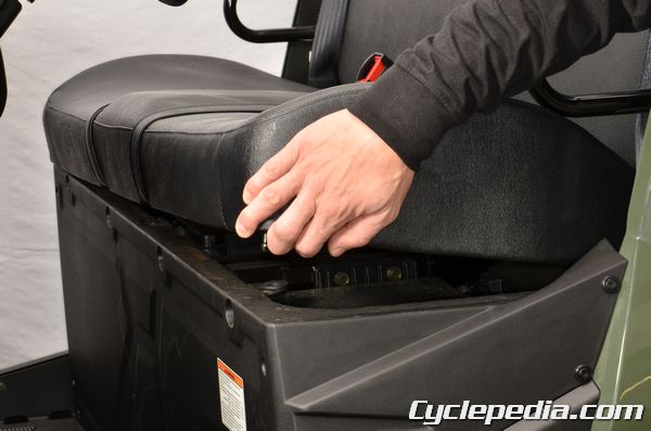
Remove the seat. See the Seat topic for more information.
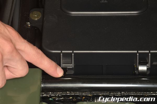
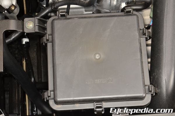
The air filter cover has seven clips. Open the air filter cover clips.
Free the tabs at the front of the cover and lift off the air filter cover.
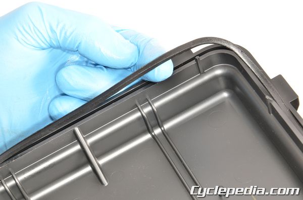
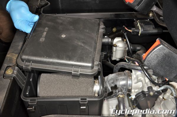
Inspect the airbox cover seal and replace it as necessary.
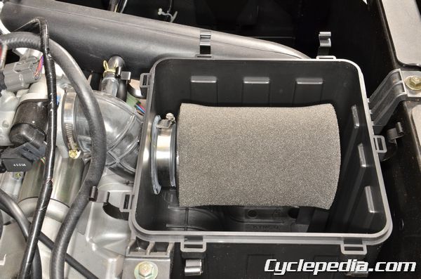
Loosen the air filter clamp screw with a flat blade screwdriver or an 8 mm socket.
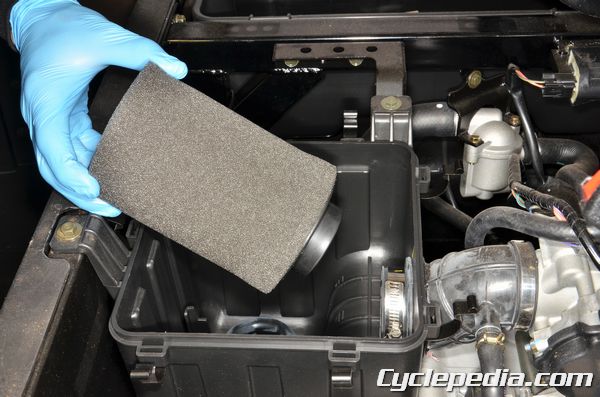
Lift out the air filter.
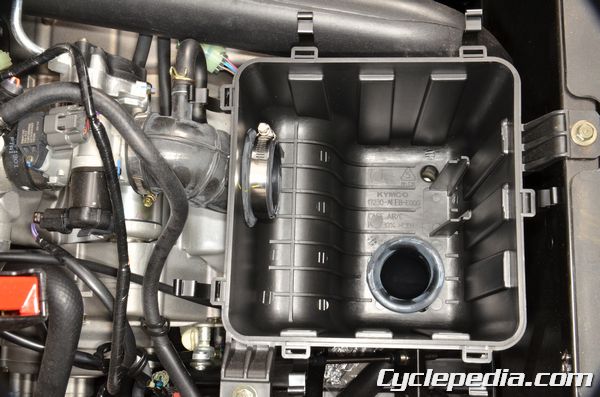
Clean out the airbox.
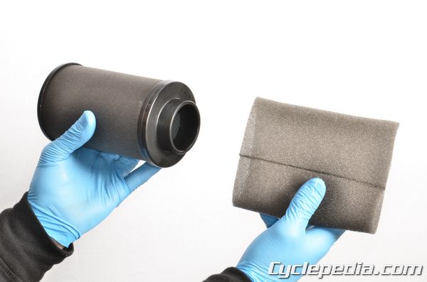
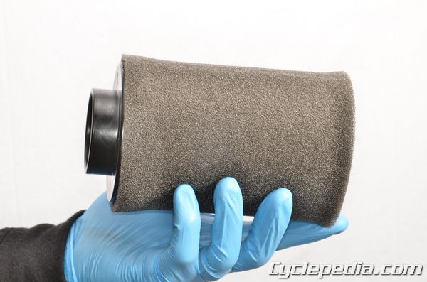
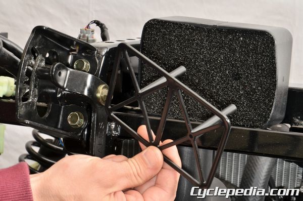
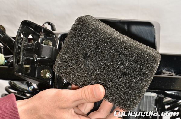
Remove the outer air filter element.
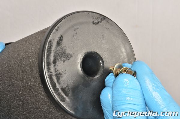
Loosen the air filter holder screw with a #2 Phillips screwdriver. Remove the screw and washers from the air filter.
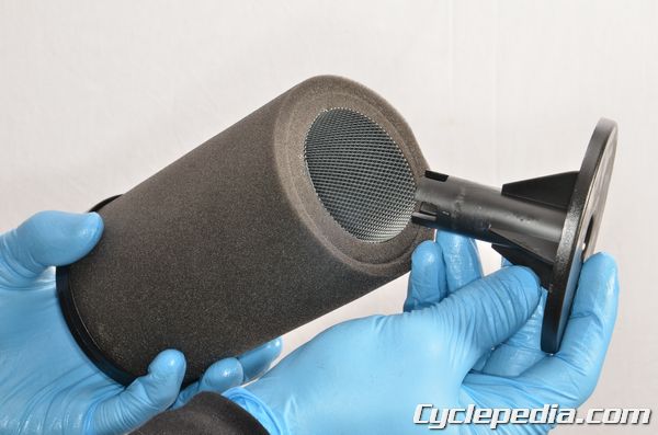
Remove the air filter holders from the air filter.
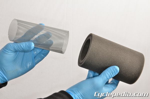
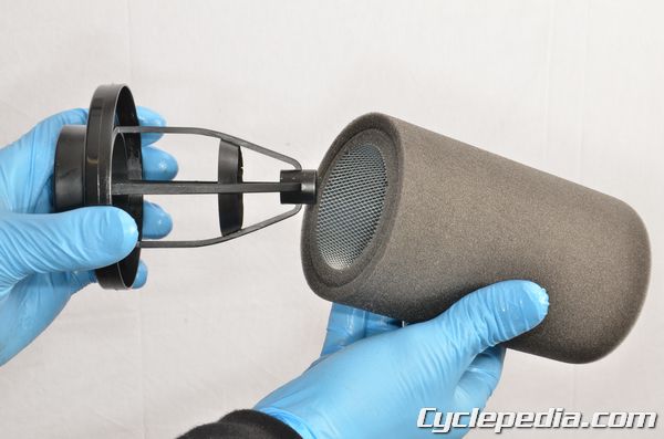
Slide out the air filter screen. Inspect the air filter for foam deterioration, tears and glue separation. Replace the air filter if any damage is found.
Air Filter Servicing
Service the inner and outer air filter elements in the same manner.
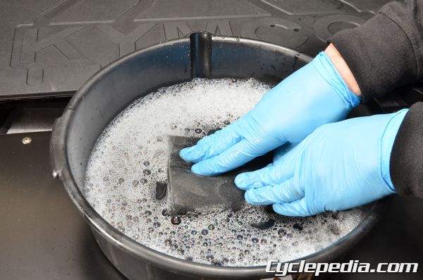
Place the filter in a container and saturate it with a foam air filter cleaner both inside and out. Products like Simple Green, dish soap, or most non-flammable solvents will work if foam filter cleaner is unavailable. If using foam air filter cleaner be sure to follow the manufacturers instructions. Let the filter soak for approximately 5 minutes or follow the cleaning product instructions if different.
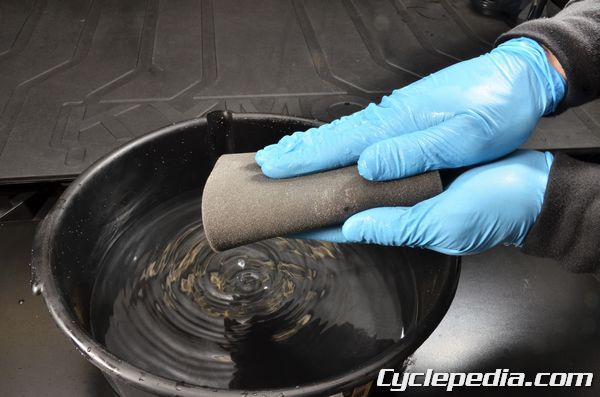
Rinse the foam filter in warm water until the water runs clear. You may squeeze the filter to remove excess cleaner and water, but do not twist it as this may tear the foam. Repeat this cleaning procedure a second time if needed.
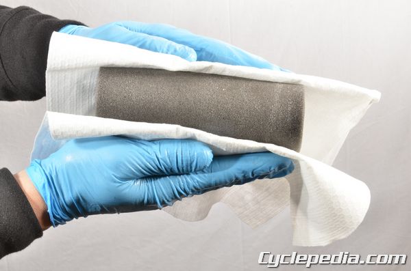
Pat the filter with a clean towel to remove most of the water.
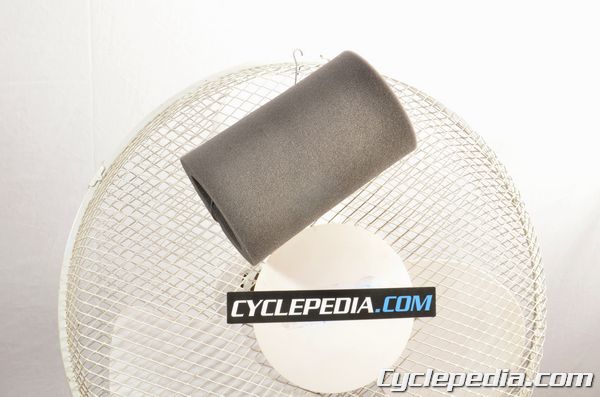
Let the filter dry completely, using a fan helps speed the drying process.
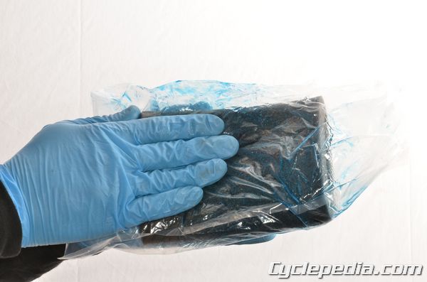
Place the air filter in a plastic bag and pour in the air filter oil, use enough oil to saturate the filter. Use a high quality foam air filter oil. Gently work the oil into the filter.
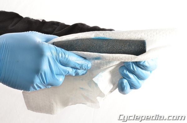
Once the oil is worked into the filter remove it from the bag and squeeze out the extra oil, do not twist it as this may tear the foam
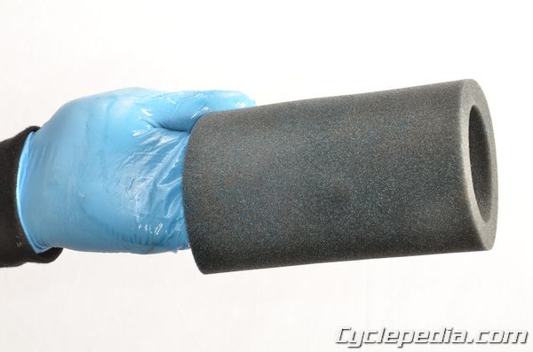
Use more towels if needed to absorb any extra oil, when your finished you should have a nice even coating of oil on your air filter.
Air Filter Installation
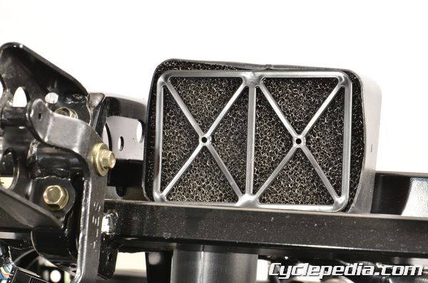
Insert the screen into the inner air filter element. Install the holder halves into each end of the inner air filter and screen.
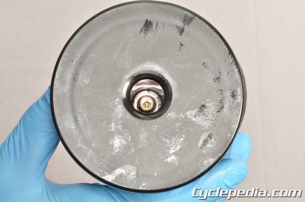
Install the air filter holder screw and washers. Tighten the air filter holder screw securely with a #2 Phillips screwdriver.
Install the outer air filter element over the inner element.
Fit the air filter into the airbox. Tighten the air filter clamp screw securely with a flat blade screwdriver or an 8 mm socket.
Install the air filter cover. Secure the air filter cover with the clamps.
Install the Seat.
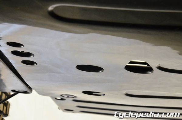
Air Filter Drain
Inspect the airbox drain tubes. Remove the tubes and drain away any fluid build up or debris that may have collected.
Inspect the air intake tube. See the Air Intake Tube topic for more information.
Air Intake Tube
SAFETY FIRST: Protective gloves and eyewear are recommended at this point.
When servicing the intake tube do not allow debris to enter the intake tube.
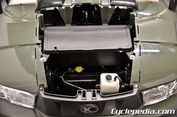
Remove the hood to access the air intake tube. See the Hood topic for more information.
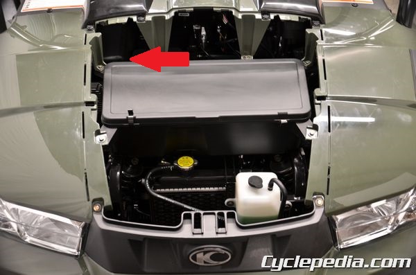
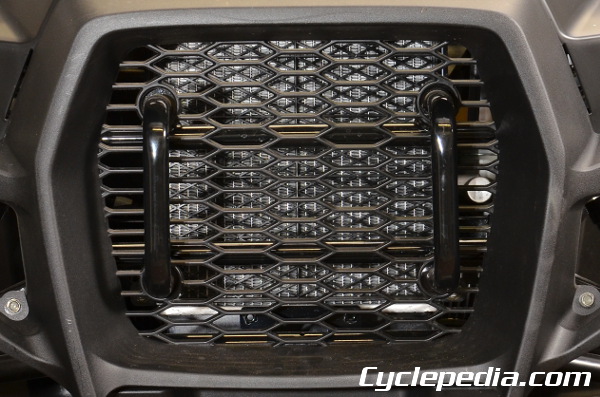
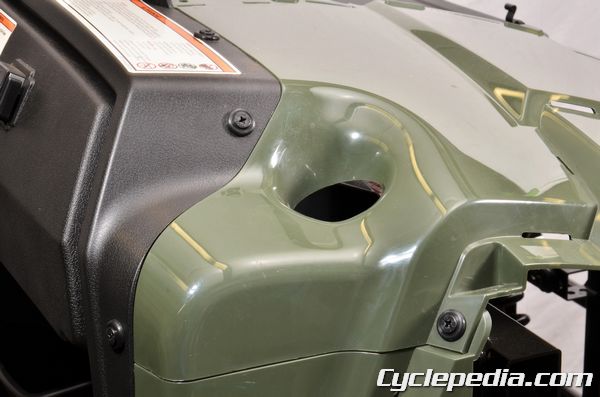
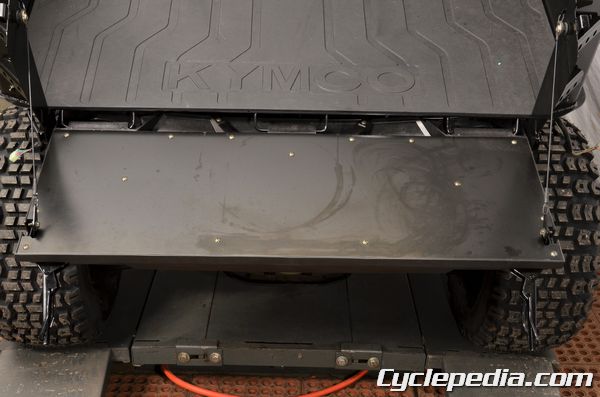
The air intake tube filter is located behind the top left corner of the front storage box. Inspect the intake tube for debris or anything restricting air flow.
Remove the front storage box to gain access to the intake tube filter. See the Front Storage Box topic for more information.
Remove the two filter cage screws with a #2 Phillips screw driver.
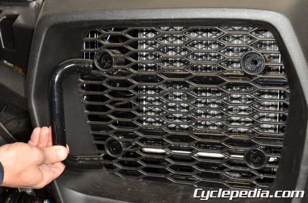
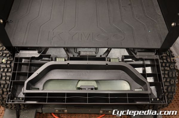
Remove the filter cage.
Remove the intake tube filter. Inspect the filter for damage or deterioration and replace as needed. Gently pat the filter or use low pressure compressed air to clean the filter.
Fit the filter into place and install the filter cage.
Install the cage screws and tighten securely.
Install the front storage box. See the Front Storage Box topic for more information.

Install the hood. See the Hood topic for more information.
Brake Fluid
SAFETY FIRST: Protective gloves and eyewear are recommended at this point.
This vehicle uses DOT 4 brake fluid. Do not mix the brake fluid types. The system should be bled whenever the brakes feel spongy, or if the brake system has been taken apart and rebuilt. Always use fresh brake fluid from a tightly sealed container.
Warning: Brake fluid is very caustic and can damage paint, chrome and plastic. Wipe up any spills immediately.
Brake Fluid Inspection
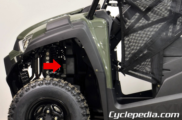
View the master cylinder reservoir.
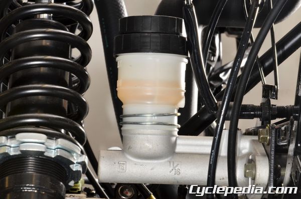
Make sure the fluid live is above the minimum mark.
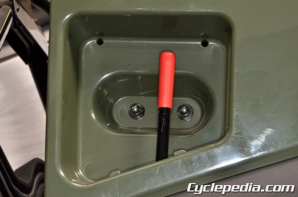
Brake Fluid Draining
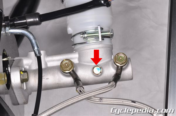
Place a suitable container under the master cylinder to catch the fluid. Remove the brake fluid drain bolt to drain the brake fluid.
Note: Do not splash brake fluid onto any rubber, plastic and coated parts. When working with brake fluid, use shop
towels to cover these parts. The front and rear brakes follow the same procedure.
Loosen the bleeder valve on the brake caliper using an 8 mm wrench. This valve is usually very tight so use a box end wrench or a 6 point socket and ratchet to prevent rounding off the head. Snug the bleeder valve back down. Place a length of 6 mm inside diameter clear hose on the bleeder valve and place the other end in a container to catch the old brake fluid. Loosen the bleeder valve and pump the brake pedal to remove the brake fluid. Stop pumping the pedal when the fluid stops flowing. Alternatively, you can use a Mighty -Vac or a similar device to suck out the old brake fluid.
Brake Fluid Bleeding
When bleeding the brakes, start from the farthest caliper and work towards the master cylinder.
Fill the master cylinder with DOT 4 brake fluid from a fresh, newly opened container and bleed the brakes.
Note: The front and rear brakes follow the same procedure.
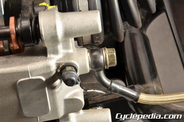
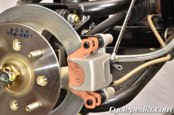
Pull off the rubber cap over the bleeder valve on the caliper you are working on.
Loosen the bleeder valve on the brake caliper using an 8 mm wrench. This valve is usually very tight so use a box end wrench or a 6 point socket and ratchet to prevent rounding off the head. Snug the bleeder valve back down. Place a length of 6 mm inside diameter clear hose on the bleeder valve and place the other end in a container.
Pump the brake pedal several times and hold the pedal down. While holding the pedal, loosen the bleeder valve. The brake pedal will travel all the way to the floor and brake fluid and/or air will come out of the bleeder valve into the 6 mm hose. Tighten the bleeder valve before releasing the brake pedal. Pump the pedal several times again and repeat the process.
Be certain to check the master cylinder reservoir occasionally to make sure the reservoir doesn’t run dry. Add more brake fluid as necessary. Continue this process until clean brake fluid comes out of the bleeder valve and there are no air bubbles. The brake pedal should feel firm.
Tighten the bleeder valves to specification and push their rubber covers over the nipples.
Brake Caliper Bleed Screw: 0.6 kgf-m, 6 N-m, 4 ft-lb
Make sure the reservoir has the proper amount of fluid. Install the master cylinder cap. Check the function of the brakes before operating the machine.
Brake Inspection
SAFETY FIRST: Protective gloves and eyewear are recommended at this point.
Brake Pad Inspection
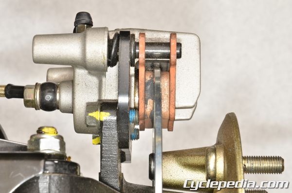
Inspect the brake pad linings for wear.
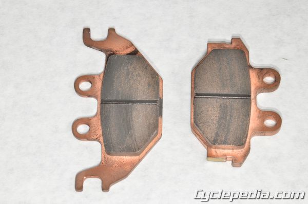
Make sure the wear doesn’t exceed the wear grooves in the linings. Replace the brake pads as a set if needed.
See the Front Brake Caliper or Rear Brake Caliper topic for more information.
Brake Fluid Inspection
Compress the brake pedal several times. The pedal should be firm. If the pedal is not firm, but mushy, the brake system requires bleeding. See the Brake Fluid topic for more information.
Remove the following components:
Place the vehicle on level ground so the master cylinder reservoir is level.
Check the level of brake fluid. Remove the cap and fill the brake fluid with DOT 4 brake fluid to the upper mark if necessary.
See the Brake Fluid topic for more information on brake fluid changing, filling and bleeding.
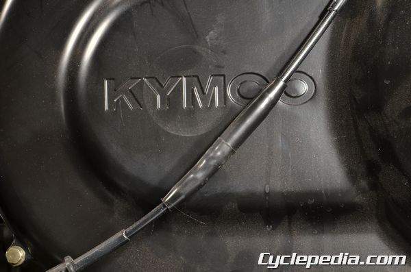
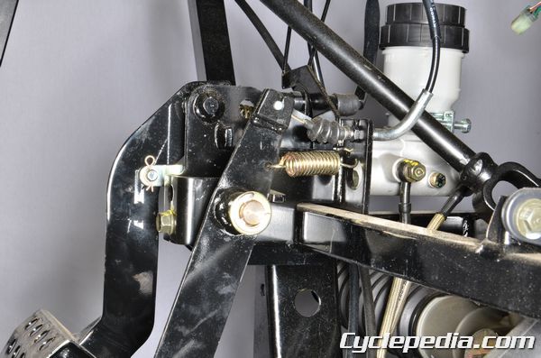
Parking Brake Inspection
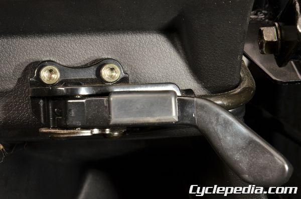
Make sure the parking brake doesn’t drag when the lever is released, and the parking brake holds when the lever is applied.
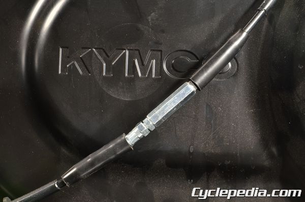
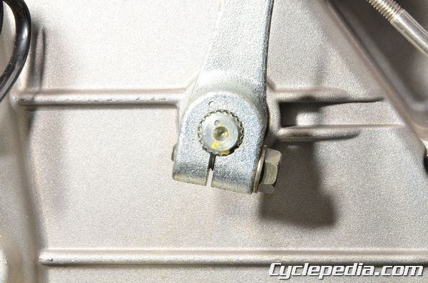
Adjust the inline cable adjuster as needed.
Trace the cable up from the parking brake until you reach the adjuster. Loosen the adjuster lock nut with a 10 mm wrench. Turn the adjuster out to decrease free-play and turn it in to increase free-play. Always check that the parking brake operates properly.
Compression Test
SAFETY FIRST: Protective gloves and eyewear are recommended at this point.
Run the engine to warm it up before conducting a compression test. Make sure your compression gauge is in good working order and does not leak. The battery must be fully charged when testing the compression.
Remove the spark plug. See the Spark Plug topic for more information.
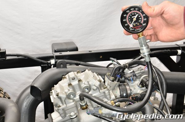
Install the compression tester into the spark plug hole using a compression gauge adapter and tighten it hand tight.
Hold the throttle wide open and use the electric starter to turn the engine over. Crank the engine until the needle on your compression gauge stops rising. This should occur in 4 to 7 seconds of engine cranking. Do not crank the engine for more than 7 seconds. Compare your reading with the specification.
Cylinder Compression Pressure: 170 – 227 psi
High compression is an indication of excessive carbon buildup on the piston or a result of performance modifications.
Low Compression Troubleshooting
- Verify the starter cranks the engine over and normal speed ~ 400 rpm
- Make sure the compression gauge is working correctly
- Make sure the throttle is fully open for testing
- Check the valve clearance – Valve Adjustment
- Inspect the valves or valve seats – Valves
- Pour 29.5 ml (1 fl oz) of fresh engine oil into the spark plug hole and retest the compression. If the compression is now in the correct range the piston and rings should be inspected. – Cylinder and Piston
Coolant
SAFETY FIRST: Antifreeze is highly toxic and can kill pets and animals if drank. Do not leave coolant where animals (including children) can get to it. Protective gloves and eyewear are recommended at this point.
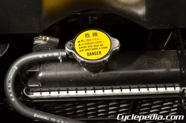
WARNING: Removing the radiator cap while the engine is hot can allow the coolant to spray out, seriously scalding you. Always let the engine and radiator cool down before removing the radiator cap.
Coolant Inspection
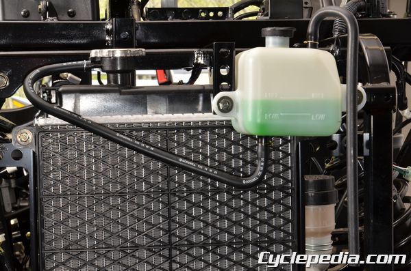
Remove the hood. See the Hood topic for more information. Place the vehicle on level ground. Check the coolant level in the coolant reservoir when the engine is cold as the coolant level will vary with engine temperature. The coolant level should be between the maximum and minimum marks. If the level is low, remove the coolant reservoir cap, and then add coolant or distilled water to raise it to the specified level.
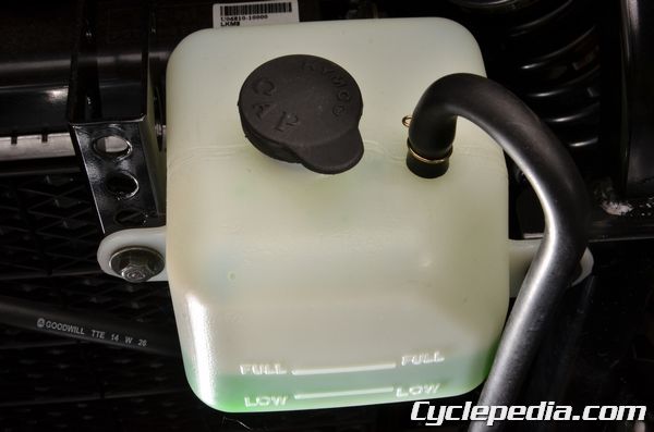
Place the machine on the level ground. Check the coolant level in the coolant reservoir when the engine is cold as the coolant level will vary with engine temperature. The coolant level should be between the maximum and minimum marks. If the level is low, remove the coolant reservoir cap, and then add coolant or distilled water to raise it to the specified level.
Coolant Replacement
Draining
- Perform this operation when the engine is cold.
Remove the following components:
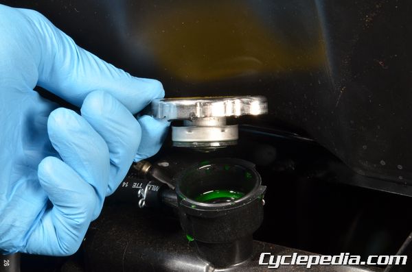
Remove the radiator cap by pushing down and turning it. Remove the radiator cap in two stages. Allow any built up pressure to vent and then open the cap all the way and remove it.
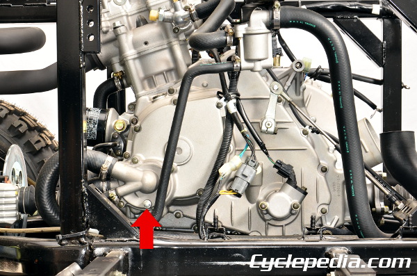
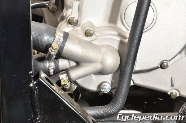
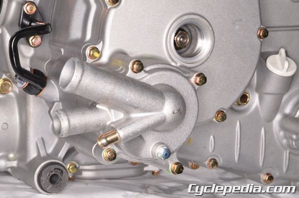
The drain plug is located on the water pump. Place a drain pan underneath the water pump and remove the drain plug using an 8 mm socket.
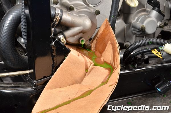
Be prepared for the coolant to spurt out quickly. Use a temporary drain guide to direct the coolant into a suitable container.
Install the drain plug with a new sealing washer and tighten it securely after the cooling system has been drained.
Remove the two mounting bolts and drain the reservoir tank. Install the tank and tighten the two mounting bolts securely.
Coolant Refilling
Coolant capacity
Radiator and engine: 2.5 liter (2.65 US qt, 2.2 Imp qt)
Reserve tank: 0.3 liter (0.32 US qt, 0.26 Imp qt)
Standard coolant concentration: 1:1 mixture with soft water
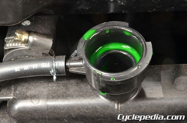
Slowly pour the new coolant into the radiator filler neck until it reaches the bottom of the neck.
Fill the reservoir tank to the FULL line. With the reservoir cap and the radiator cap off, start the engine and let it run for several minutes. Blip the throttle and rev the engine a few times. This will purge any air out of the cooling system. Add coolant to the radiator and the reservoir tank as needed.
Install the reservoir cap and the radiator cap and bring the engine up to operating temperature. Check the level of the coolant in the reservoir tank and add coolant if necessary. Do not remove the radiator cap with the engine hot!
Engine Oil
SAFETY FIRST: Protective gloves and eyewear are recommended at this point.
Engine Oil Inspection
Start the engine and let it warm up for 2 – 3 minutes. Park the vehicle on a level surface. Stop the engine and allow the oil to settle for at least a minute.
Remove the seat. See the Seat topic for more information.
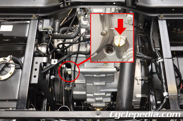
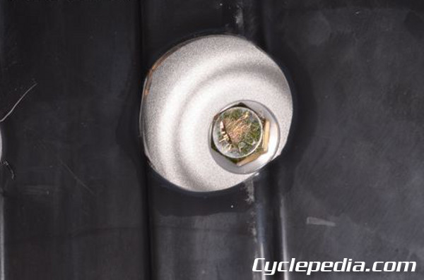
The dipstick is located on the generator cover.
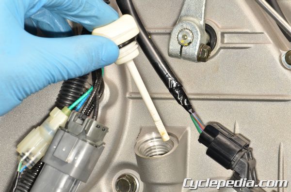
Unscrew the dipstick/ filler cap. Remove the dipstick and clean away the oil. Make sure the dipstick O-ring is in good condition. Insert the dipstick and thread it in. Remove the dipstick and inspect the oil level.
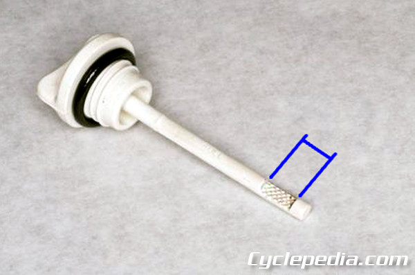
The oil level should be in the textured area of the stick. If the oil level is low add more of the same type and brand of oil to the engine through the dipstick/filler hole. Use a long funnel to reach the hole. If the oil level is significantly above the textured area drain some of oil with the drain plug.
Engine Oil Servicing
Start and run the engine for a minute or two, this will heat the engine and allow the oil to drain out faster and more completely.
NOTE: Hot engine oil can burn you, take precautions not to touch the oil when draining.
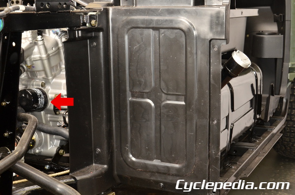
Place a drain pan under the oil filter and drain plug.
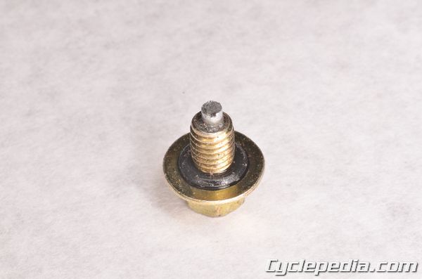
Loosen the drain plug with a 19 mm socket.
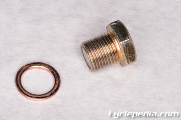
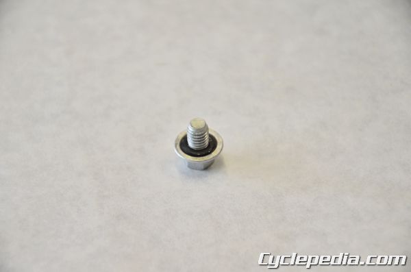
Remove the drain plug and sealing washer. Discard the sealing washer.
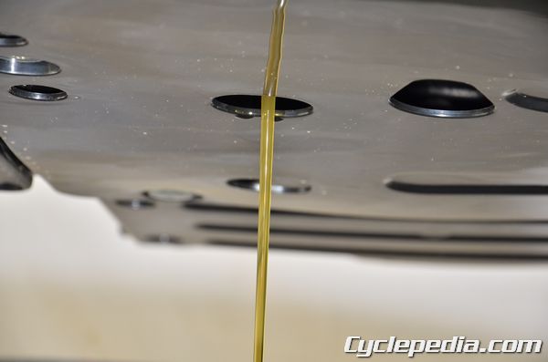
Allow the engine oil to drain into the drain pan. Remove the dipstick/filler cap to speed the draining of the oil.
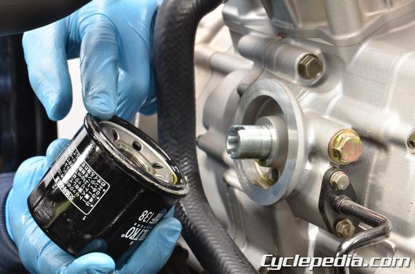
Remove the right rear wheel for better access to the oil filter. See the Wheels and Hubs topic for more information.
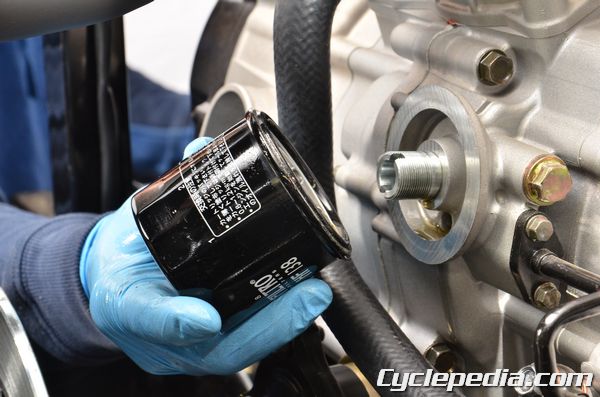
Use an oil filter wrench and loosen the oil filter cartridge. Remove the oil filter cartridge.
Special Tool – Oil Filter Wrench: E052
Install the oil drain plug with a new sealing washer. Tighten the plug to specification with a 19 mm socket.
Engine Oil Drain Plug: 26.5 Nm, 2.7 kgf-m, 19.5 ft-lb
Apply fresh engine oil to the rubber oil filter seal.
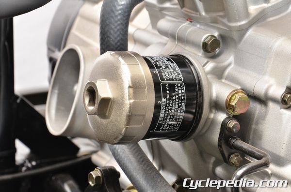
Install the oil filter onto the engine and tighten it securely by hand. Make sure the seal is making good contact with the engine. Torque the filter to specification with a filter wrench.
Oil Filter Torque: 10 Nm, 1.0 kgf-m, 7.2 ft-lb
Engine Oil Strainer Screen
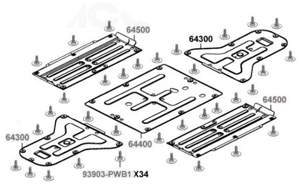
Remove the skid plate. See the Skid Plates topic for more information.
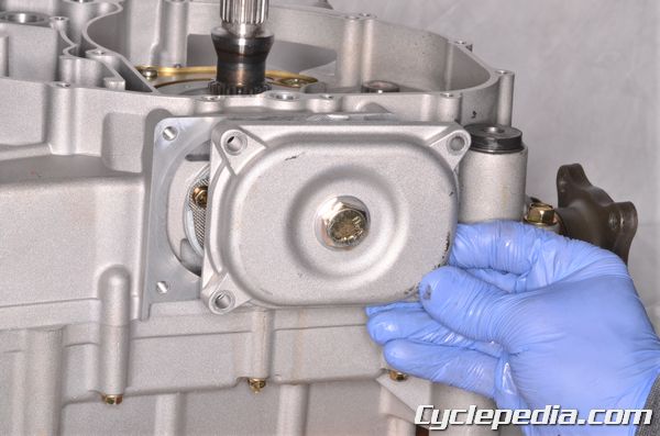
Remove the four oil strainer cover bolts with an 8 mm socket.
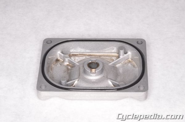
Remove the oil strainer cover. Inspect the strainer cover O-ring and replace it as needed.
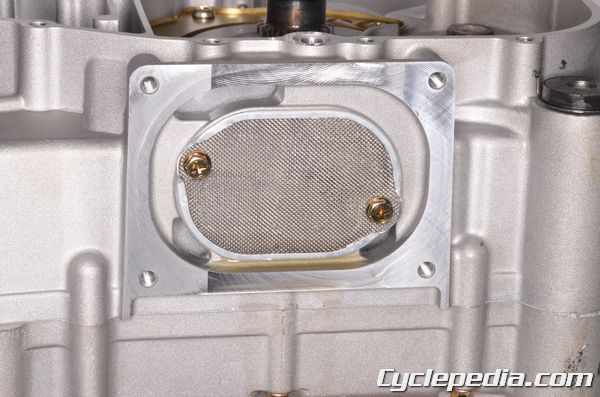
Remove the two oil filter strainer screen bolts with an 8 mm socket.
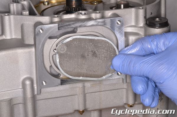
Check the oil strainer screen for metal debris accumulation that could indicated engine damage. Clean the screen with a high flash point solvent and compressed air.
NOTE: Always wear safety glasses when using compressed air and never point it directly at yourself or anyone else.
Apply fresh engine oil to the strainer screen O-ring.
Install the strainer screen. Tighten the two strainer bolts securely with an 8 mm socket.
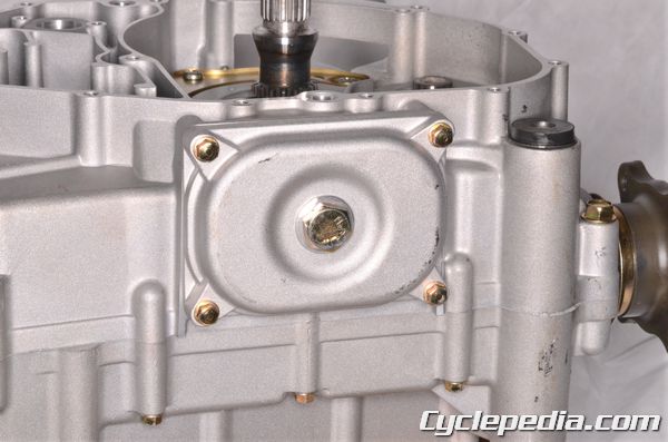
Install the strainer screen cover. Install the four strainer screen cover bolts and tighten them securely with an 8 mm socket.
Install the skid plate. See the Skid Plates topic for more information.
Oil capacity: 2.85 L
Oil exchanging capacity: 2.2 L
After draining and oil Filter cartridge change: 2.4 L
Engine Oil (Recommended): SAE 5W-30 [motorcycle or ATV specific]
Caution: Any oil used in place of the recommended oil could cause serious engine damage. Do not use oils which contain graphite or molybdenum additives. These oils can adversely affect clutch operation. Also, not recommended are racing, vegetable, non-detergent, and castor-based oils.
Add the proper type and quantity of oil and install the oil filler cap/dipstick. Start the engine and let it run for several minutes. Check for any oil leaks. Check the oil level as describe above. If the oil level is too high drain the excess oil from the oil drain bolt.
Engine Oil Pressure Check
Make sure the engine is up to operating temperature before checking the oil pressure.
1. Connect the tachometer to the engine.
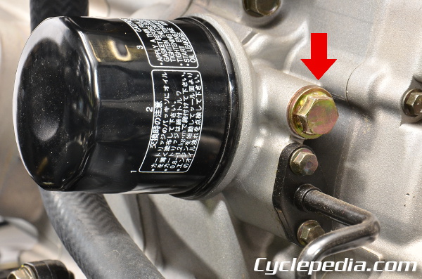
2. Remove the oil pressure plug. Connect the oil pressure test kit to the oil pressure plug hole.
Some oil seepage may occur when installing the oil pressure gauge. Wipe up oil residue with a cloth.
3. Start the engine and run it at 3000 RPM. The oil pressure gauge must read as specified.
Standard: 16-21 psi
Oil Temperature: 60 °C (140 °F)
If the oil pressure is lower than specified, check for low oil level, defective oil pump, and oil leaks.
Whenever internal engine components wear excessively or break and whenever oil is contaminated, the oil pump should be replaced. The oil pump is not a serviceable component. To replace the oil pump see the Oil Pump topic.
If the oil pressure is higher than specified, check for too heavy engine oil weight, clogged oil passage, clogged oil filter, or improper installation of the oil filter.
Final Drive Gear Oil
SAFETY FIRST: Protective gloves and eyewear are recommended at this point.
Final Drive Gear Oil Inspection
Place the vehicle on a level surface.
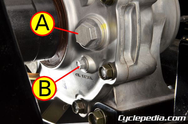
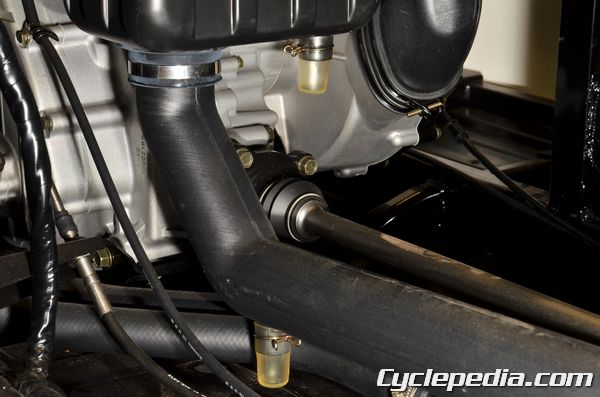
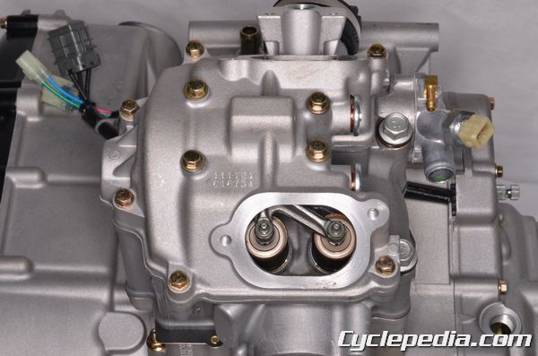
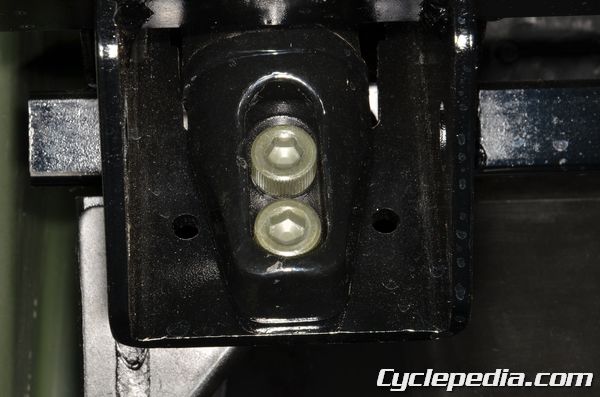
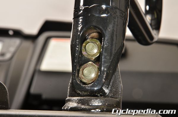
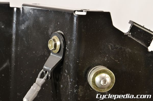
The front and rear final drive gear housings have an oil level check bolt (B) and a filler cap (A).
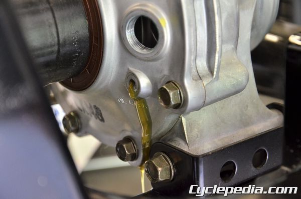
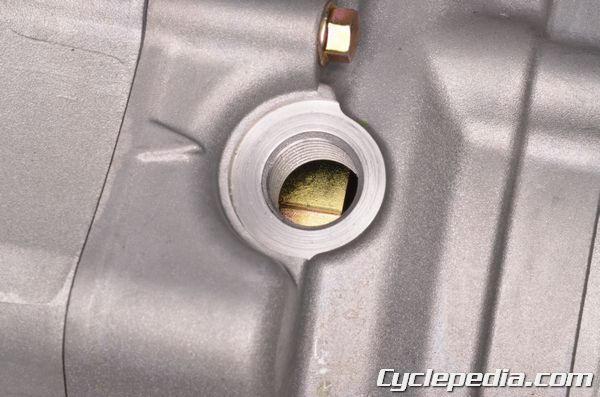
Remove the oil check bolt with an 8 mm socket. It is not necessary to remove the filler cap to check the oil level. The oil level should be even with the check bolt hole so that a little bit runs out when you remove it. If additional oil is needed see the Oil Filling section of this topic.
Inspect the check bolt O-ring and replace it as needed. Install the check bolt and tighten it securely with an 8 mm socket.
Final Drive Gear Oil Draining
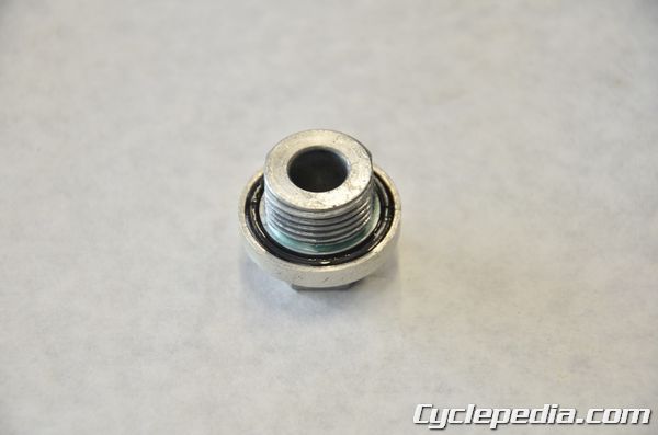
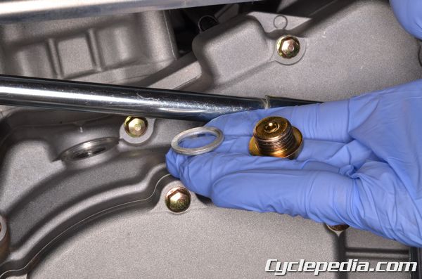
Remove the filler cap with a 17 mm socket. Inspect the filler cap O-ring and replace it as needed.
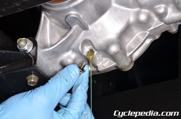
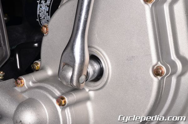
Place a suitable oil drain pan under the drain bolt. Remove the drain bolt with an 8 mm socket.
Once the oil drains out completely, install the drain plug with a new O-ring and tighten it securely within 8 mm socket.
Final Drive Gear Oil Filling
Fill the final drive with the specified quantity of oil. The oil should reach the height of the check bolt hole.
Recommended Oil: SAE 80-90
Front Final Drive Gear Oil
At disassembly: 270 ccc
At change: 250 cc
Rear Final Drive Gear Oil
At disassembly: 250 cc
At change: 230 cc
Install the oil level check bolt (B) and the filler cap (A). Tighten the oil level check bolt and filler cap securely.
Lubrication
SAFETY FIRST: Protective gloves and eyewear are recommended at this point.
Check the cable operation. Lubricate or replace if unsmooth operation.
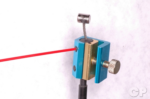
Use a cable lubricator to lubricate all control cables with a quality cable lube.
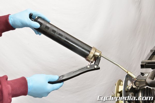
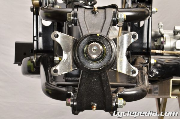
Use the grease nipples located on the rear knuckles pivots to lubricate these components with lithium based grease.
Spark Plug
SAFETY FIRST: Protective gloves and eyewear are recommended at this point.
Spark Plug Removal
Open the cargo bed.
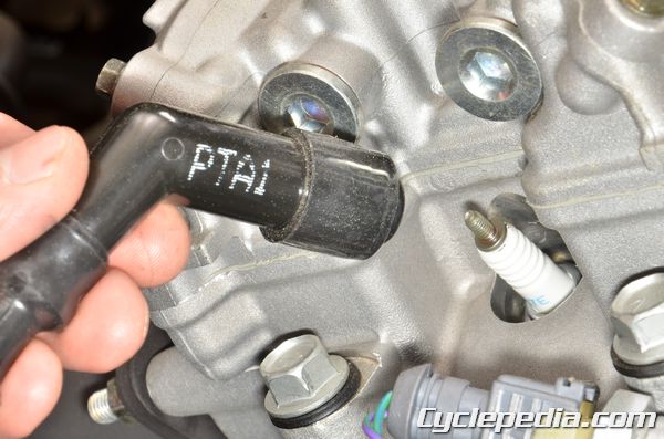
Pull the spark plug cap off of the spark plug. Clean off the area surrounding with compressed air or a shop towel to make sure debris doesn’t get into the combustion chamber when the spark plug is removed.
NOTE: Always wear safety glasses when using compressed air and never point it directly at yourself or anyone else.
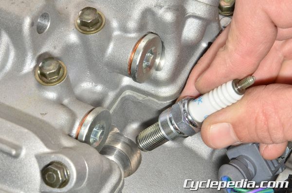
Remove the spark plug using a 5/8 in. deep well spark plug socket.
Spark Plug Inspection
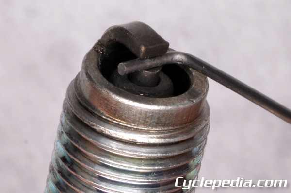
Inspect the color of the porcelain nose of the spark plug. The color of the spark plug can indicate how the mixture is burning. A white colored plug shows a lean mixture, where a dark plug shows a rich mixture. See the Spark Plug Troubleshooting Chart for more information.
If the plug is dirty or has carbon build up it can be cleaned with small wire brush. Do not hesitate to replace a spark plug if the gap is excessive or if the plug appears burnt or dirty. Always check the gap of the spark plugs before installation. If the gap needs to be adjusted bend the ground electrode carefully.
Spark plug gap: 0.8-0.9 mm
Spark plug: Standard CR6E (NGK)
Spark Plug Installation
Thread the spark plug in by hand to make sure it doesn’t cross-thread.
Tighten the spark plug to specification with a deep well 5/8 in. spark plug socket. Do not over tighten the spark plug. The cylinder head is made out of soft metal, and it can be easily damaged.
Spark Plug Torque: 10 Nm, 1.0 kgf-m, 8.7 ft-lb

Install the spark plug cap onto the spark plug.
Steering and Suspension
SAFETY FIRST: Protective gloves and eyewear are recommended at this point.
Steering and Suspension Inspection

Place the vehicle on level ground. Move the suspension up and down and make sure it moves smoothly and returns to its original position. See the Front Suspension and Rear Suspension chapters for more information.
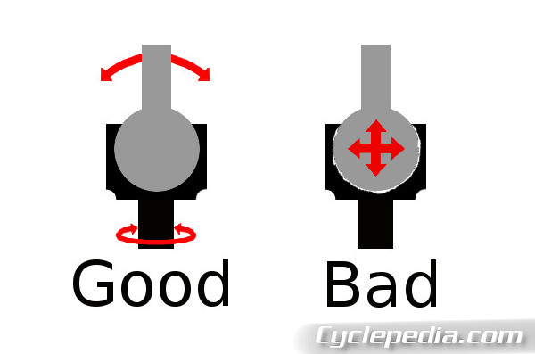
Inspect the tie-rod ends. Replace the tie-rod ends if either tie-rod end has any play. See the Steering Rack topic for more information on the tie-rods.
Toe-In Adjustment
Place the vehicle on a level surface and check the air pressure is in specification before proceeding. See the Tires topic for more information.
Have the steering wheel pointing straight ahead.
Place a mark on the center front of both of the front tires.
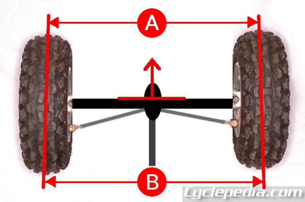
Measure the distances between the center marks on the tires and call this measurement A. Rotate the marks so that they are now at the back of the tire. Measure the marks again on the rear of the tires. Call the rear measurement B.
Find the difference between A from B to get the toe-in measurement.
B – A = toe-in
The toe-in should be 0 ~ 15 mm (0 ~ 0.59 in)
Steering and Suspension Adjustment
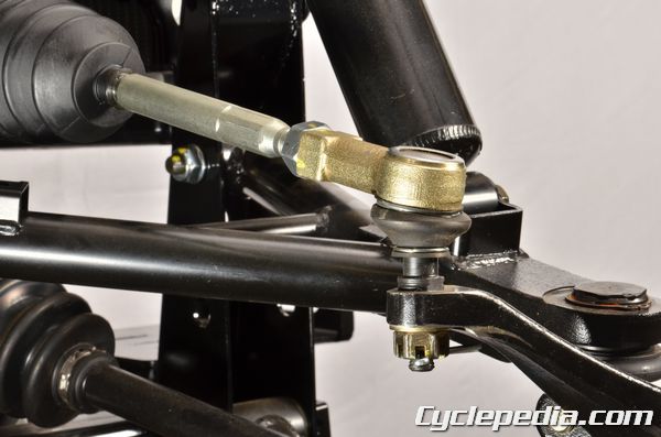
Mark both tie-rods so the amount the rod is turned can be observed.
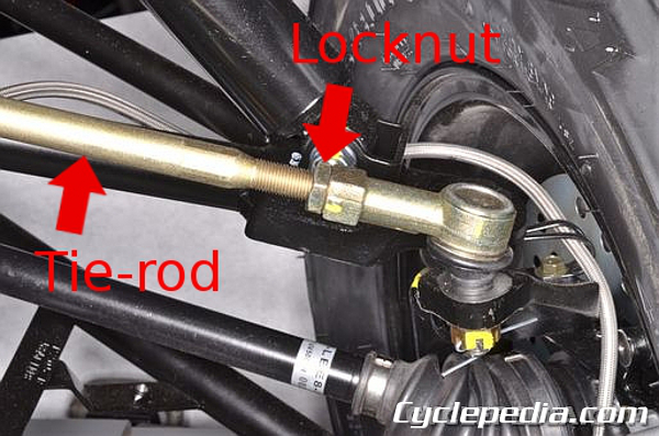
Loosen the left and right outer tie-rod locknuts with a 19 mm wrench. Hold the tie-rod end and turn the tie-rod. Turn both the tie-rods evenly until the toe-in is within specification. Moving the tie-rods out towards the wheels will increase toe-in. Moving the tie-rods towards the center will decrease toe-out. Temporarily tighten the tie-rod locknuts with a wrench and re-check the toe in.
Toe-in: 0 – 15 mm (0 – 0.6 in).
Tighten the tie-rod locknuts to specification with a 19 mm wrench.
Tie-rod lock nut: 4.0 kgf-m (40 Nm, 28 ft-lb)
After adjusting the toe-in, take the vehicle for a slow test ride. If the machine pulls to the left or right when the steering wheel is facing straight ahead the toe-in needs to be readjusted more evenly.
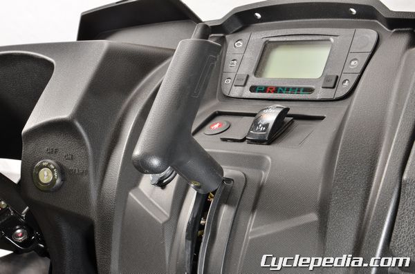
Throttle Free Play
SAFETY FIRST: Protective gloves and eyewear are recommended at this point.
Throttle Free Play Inspection
Inspect the throttle free play by operating the throttle pedal. The end of the throttle pedal should travel 3 – 5 mm (0.12 – 0.20 in) before the cable slack is taken up and the throttle begins to open.
When the throttle pedal is pushed all the way in and released it should return to its resting position quickly. Also, the throttle operation should be smooth.
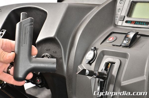
Throttle Free Play Adjustment
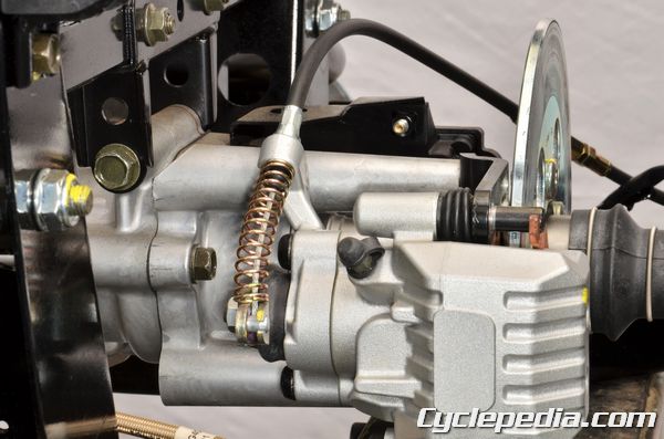
Inline Adjustment
Remove the seat. See the Seat topic for more information.
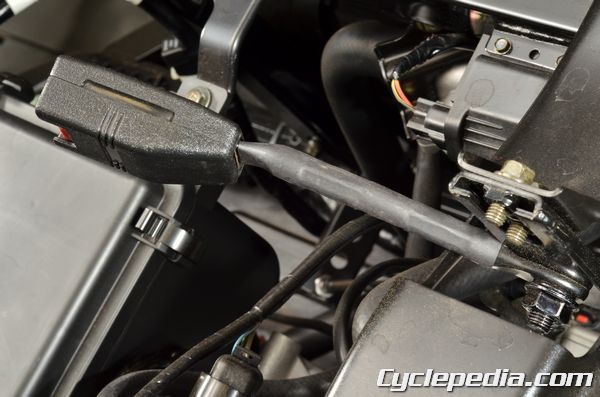
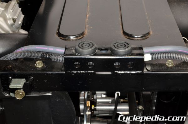
Locate the throttle cable adjuster near the CVT cover. Pull back the rubber covers from the throttle cable adjuster. To adjust the throttle free play loosen the lock nut on the throttle cable with an 8 mm wrench and turn the adjuster with an 8 mm wrench. Turn the adjuster out to decrease free-play and turn it in to increase free-play. Always check that the throttle operates freely and returns properly. Tighten the lock nut securely.
Return the rubber covers over the throttle cable adjuster.
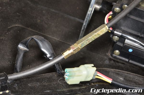
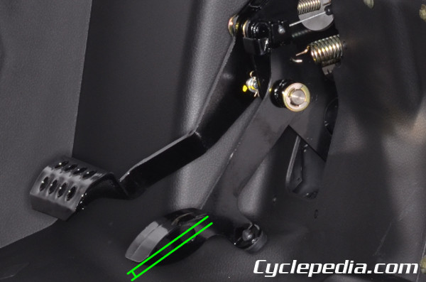
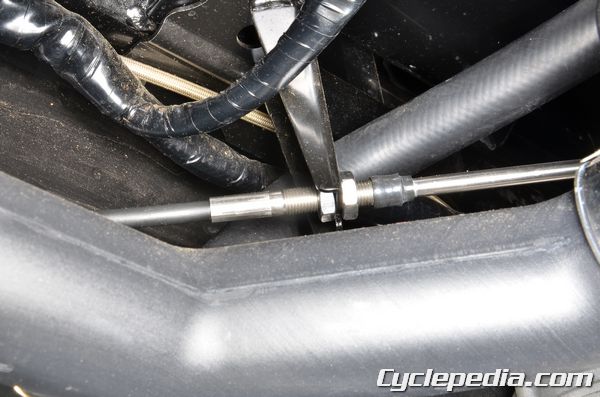
Pedal End Adjustment
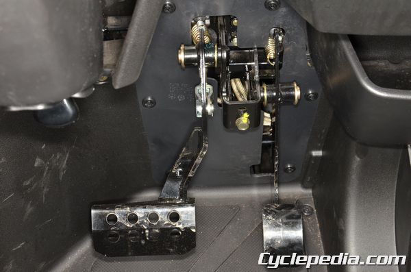
Remove the pedal plate trim clips. Remove the pedal plate.
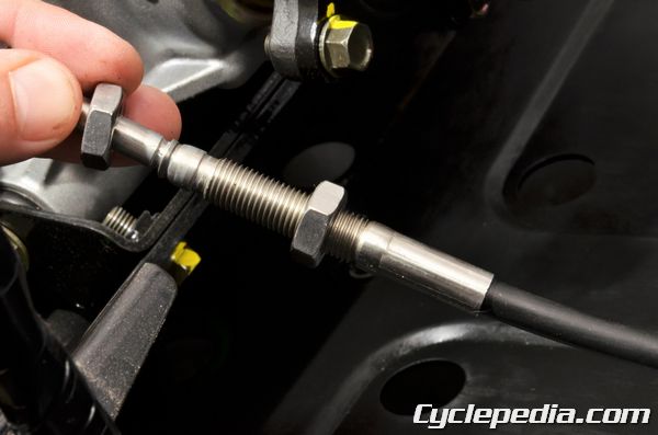
The throttle cable free play can be adjusted near the pedal end of the cable. Use a 10 mm wrench to turn the nuts.
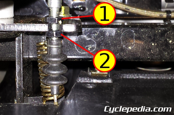
Loosen the locknut (1) and turn the adjuster nut (2) to set the proper throttle free play. Tighten the nuts locknut securely when finished.
Install the pedal plate and trim clips.
Tires and Wheels
Inspect the tires for correct tire pressure. An under or over inflated tire can increase tire wear and affect steering. Maintain correct tire pressure for safety and to maximize tire life. Vehicle instability can also be caused by improper tire size.
Tire Size
Front: 25X8-12
Rear: 25X10-12
Tire Pressure
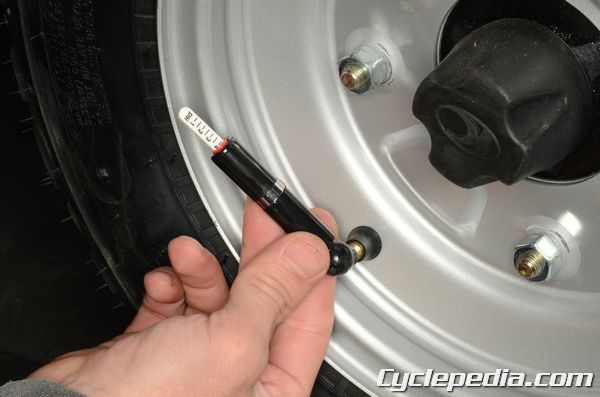
Check the tire pressure with a low pressure gauge.
Front: 0.7 kgf/cm2 (10 psi)
Rear: 0.98 kgf/cm2 (14 psi)
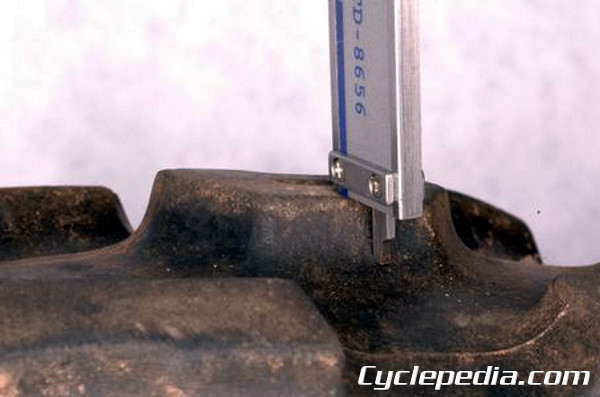
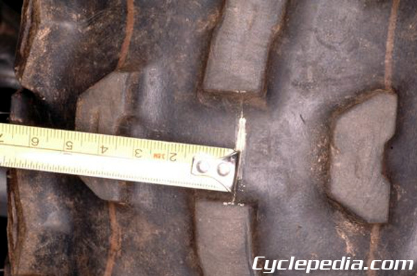
The tread depth should be even and sufficient with a minimum depth of 3 mm.
Valve Clearance
SAFETY FIRST: Protective gloves and eyewear are recommended at this point.
The valve clearance should only be checked when the engine is cold (below 35°C or 95°F).
Valve Clearance Inspection
Remove the following components in order to inspect the valve clearance:
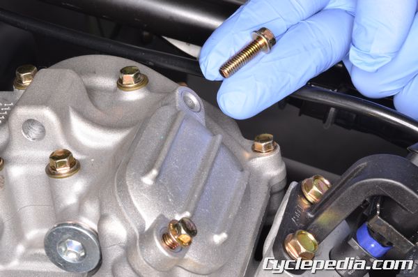
The valve adjuster covers are each held on with two bolts. Remove the valve adjuster cover bolts with an 8 mm socket.
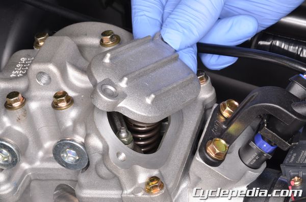
Lift off the valve adjuster covers.
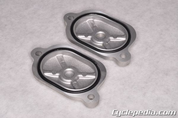
Inspect the valve adjuster cover O-rings and replace them as needed.
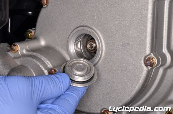
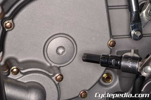
Remove the crankshaft cap on the stator side of the engine with a 10 mm Allen socket. Inspect the O-ring and replace it as needed.
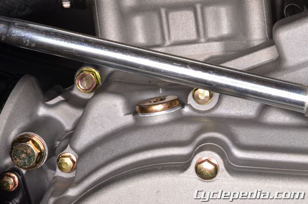
Loosen the timing inspection plug with an 8 mm Allen. Remove the timing inspection plug and sealing washer.
Turn the crankshaft counterclockwise with a 22 mm socket.
Align the “T” mark on the flywheel with the index mark on the crankcase cover. This shows the piston is at Top Dead Center (TDC).
The piston should now be at TDC (Top Dead Center) on the compression stroke. You can make sure that it is on the compression stroke by checking that there is some slack in the rocker arms. If the rocker arms are rigid, rotate the crankshaft 360 degrees counterclockwise until the “T” mark is once again aligned with the notch on the case cover. There should now be slack in the rocker arms and the piston should be at TDC on the compression stroke.
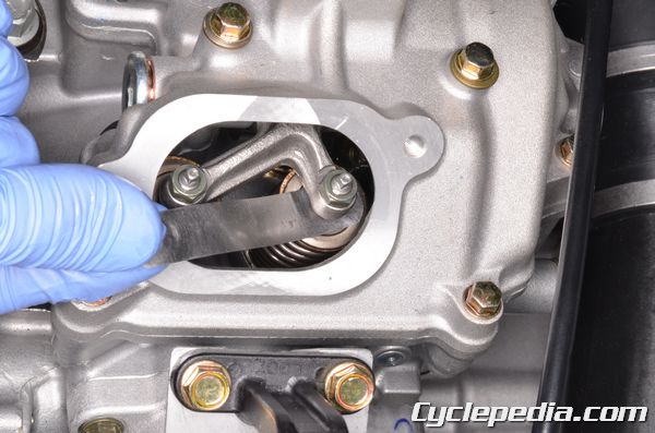
Measure the valve clearance with a thickness feeler gauge. Insert the feeler gauge between the adjusting screw and the valve stem. The clearance is correct when there is a light drag on the feeler gauge. If the clearance is out of spec move on to the adjustment section.
Intake: 0.1 mm (0.004 in) (cold)
Exhaust: 0.17 mm (0.007 in) (cold)
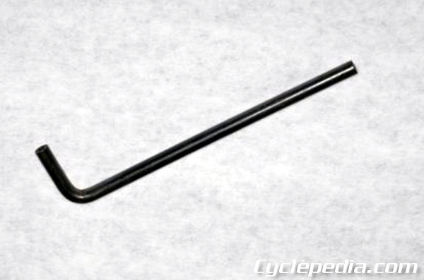
Use a valve adjuster tool to adjust the valves.
Special Tool- Valve Adjuster: A120E00036
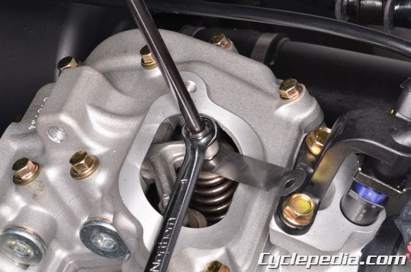
Loosen the valve adjuster locknut with a wrench. Use the valve adjuster tool to turn the adjuster in or out. If the valve clearance is too tight back out the valve adjusting screw with the valve adjustment tool. If the clearance is too loose turn in the valve adjusting screw until there is a light drag on the feeler gauge. Hold the adjusting screw locknut in place with the wrench to make sure it doesn’t interfere with the adjustment. Hold the adjuster in place when you tighten the locknut. Always recheck the clearance after tightening the locknut.
Tappet Adjustment Nut: 10 Nm, 1.0 kgf-m, 6.5 ft-lb
Install the timing inspection plug with a new sealing washer. Tighten it securely with an 8 mm Allen.
Make sure the crankshaft cap O-ring is in good condition. Apply fresh engine oil to the O-ring. Install the crankshaft cap. Tighten the crankshaft cap securely with a 10 mm Allen socket. Do not over tighten this cap.
Make sure the valve adjuster cover O-rings are in good condition. Apply a light coat of fresh engine oil to the O-rings. Fit the valve adjuster cover into place. Install the valve adjuster cover bolts. Tighten the bolts securely with an 8 mm socket.
Install the following components:
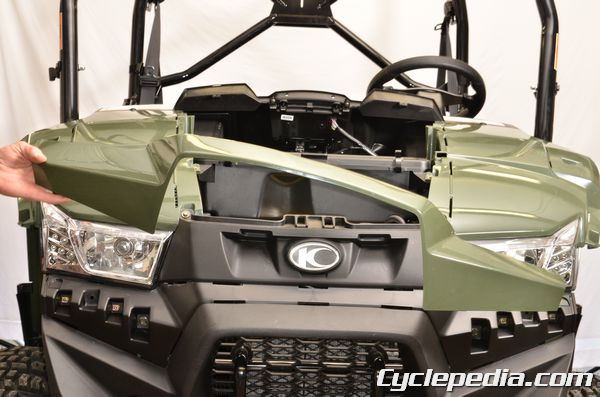
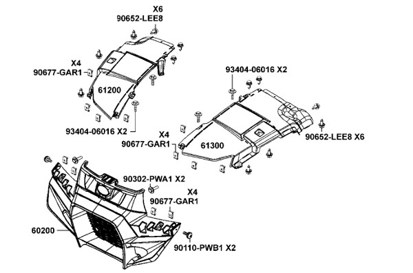
Hood
SAFETY FIRST: Protective gloves and eyewear are recommended at this point.
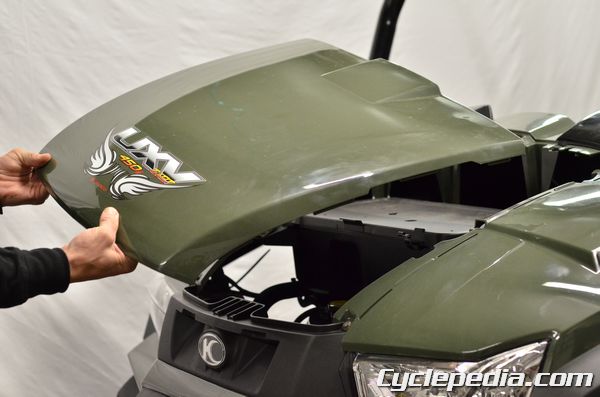
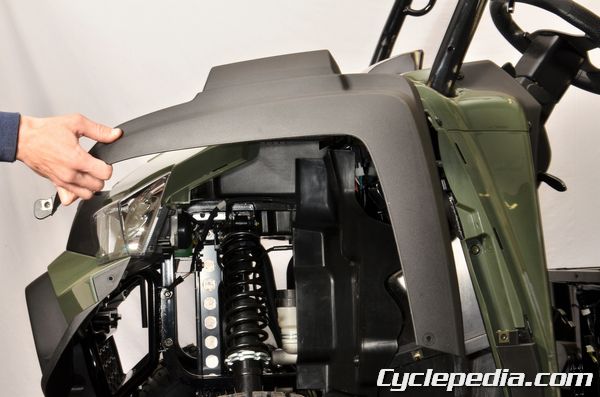
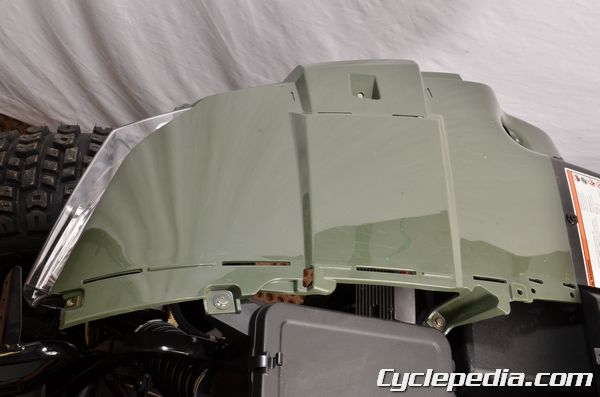
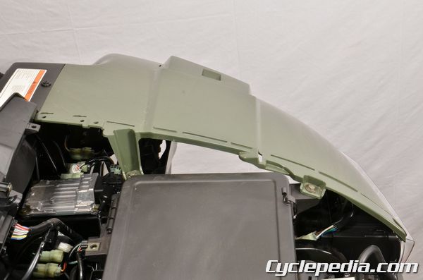
Hood Removal
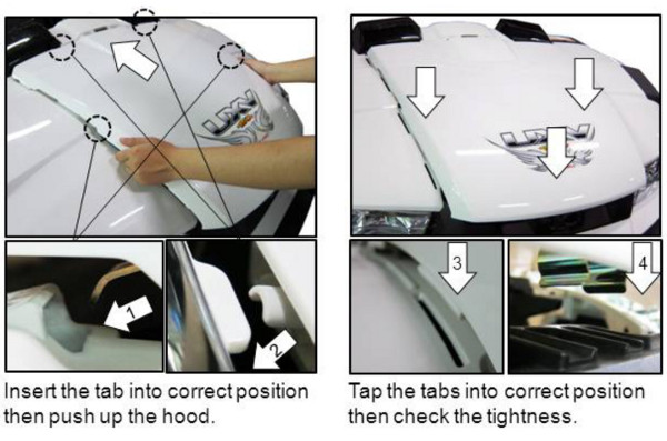
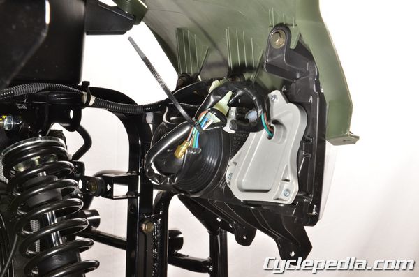
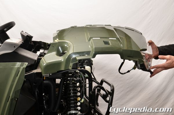
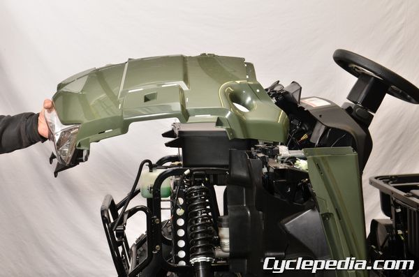
Pull up on the front of the hood and then move it forward and off of the vehicle.
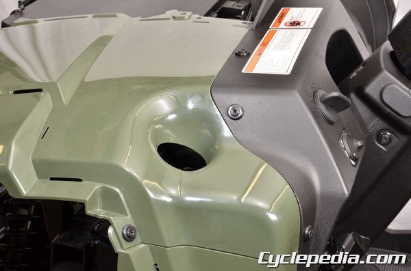
Hood Installation
Fit the tabs into place on installation.
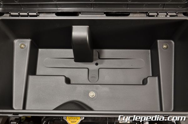
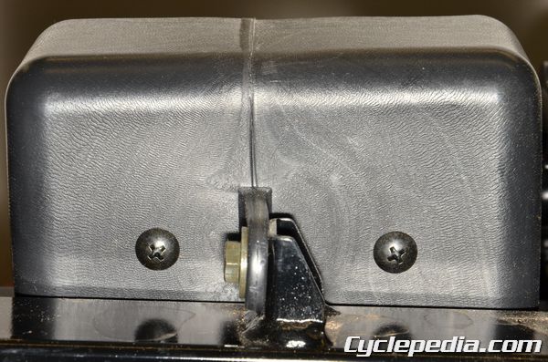
Front Storage Box
SAFETY FIRST: Protective gloves and eyewear are recommended at this point.
Remove the hood. See the Hood topic for more information.
Remove the six bodywork bolts with a 10 mm socket.
Release the latches and open the storage box lid. Remove the center bolt with a 10 mm socket and the two screws with a #3 Phillips. Remove the front storage box.
Assembly is the reverse of disassembly.
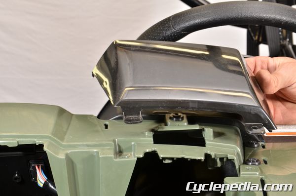
Instrument Cover
SAFETY FIRST: Protective gloves and eyewear are recommended at this point.
Remove the following components:
Remove the two parking brake lever bolts with a 5 mm hex socket.
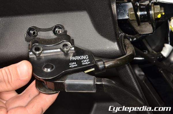
Remove the parking brake lever.
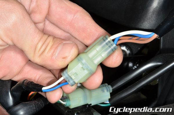
Unplug the headlight switch connector.
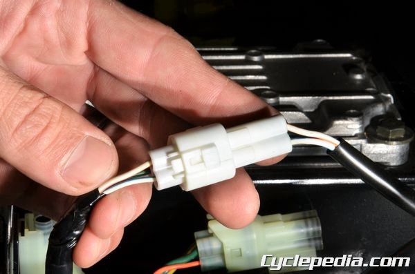
Unplug the 2WD/4WD switch connector.
Unplug the display meter connector.
Unplug the seat belt light connector.
Unplug the 12V acc. power connectors.
Unplug the ignition switch connector.
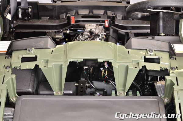
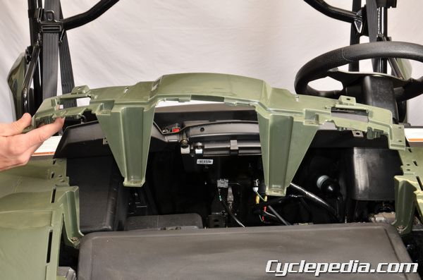
Lift off the instrument cover.
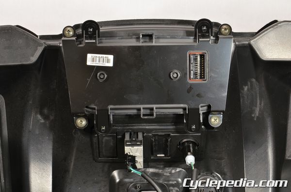
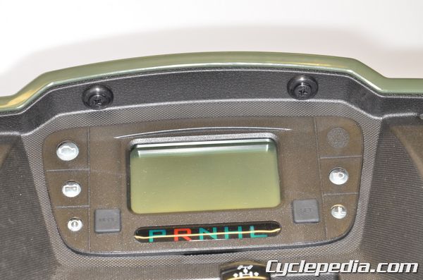
Remove the four screws to remove the display meter from the cover.
Assembly is the reverse of disassembly.
Seat
SAFETY FIRST: Protective gloves and eyewear are recommended at this point.
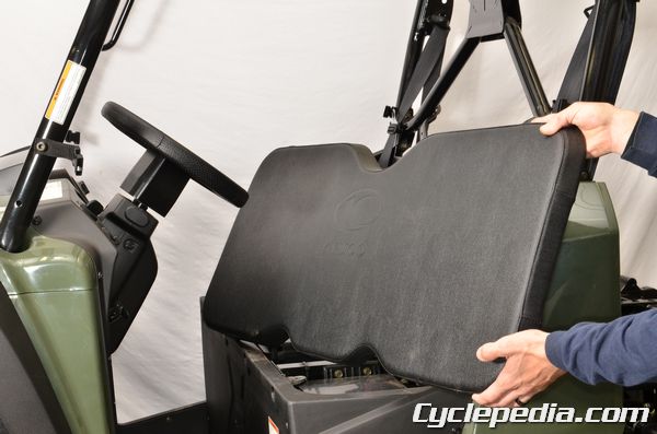
Cushion
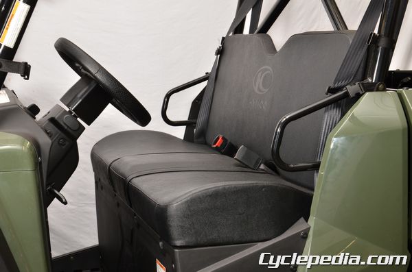
Note how the seat cushion is positioned before removal.
Pull up on the seat cushion to free it.
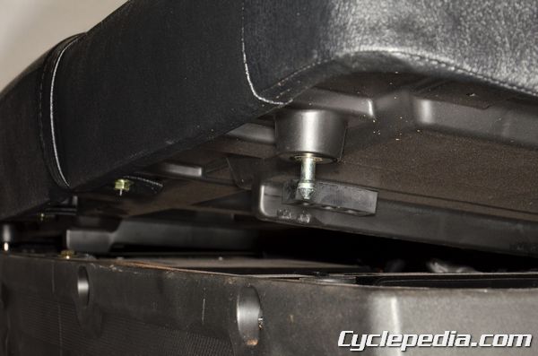
Free the seat cushion posts from their grommets.

Remove the seat cushion.
Assembly is the reverse of disassembly.
Backrest
Lift up the cargo be to access the back of the seat backrest. Remove the nuts from the back of the seat backrest.
Remove the seat backrest from the vehicle.
Assembly is the reverse of disassembly.
Headrest
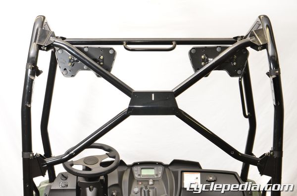
This vehicle has two headrests.
Remove the screws with a #3 Phillips screwdriver to remove the headrests.
Assembly is the reverse of disassembly.
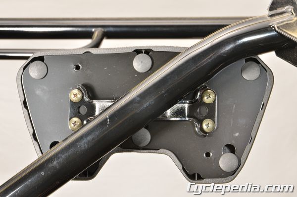
Seat Bracket
Note the location of the seat bracket bolts.
Remove the seat bracket bolts with a 10 mm socket.
Remove the seat bracket.
Assembly is the reverse of disassembly.
Seat Belts
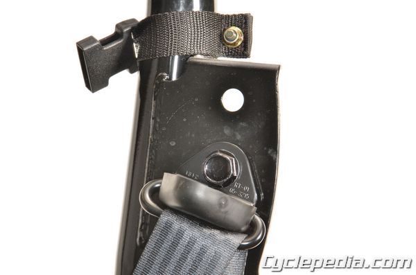
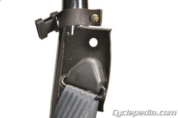
Remove the upper seat belt cover. Hold the seat belt bolt with a 17 mm socket.
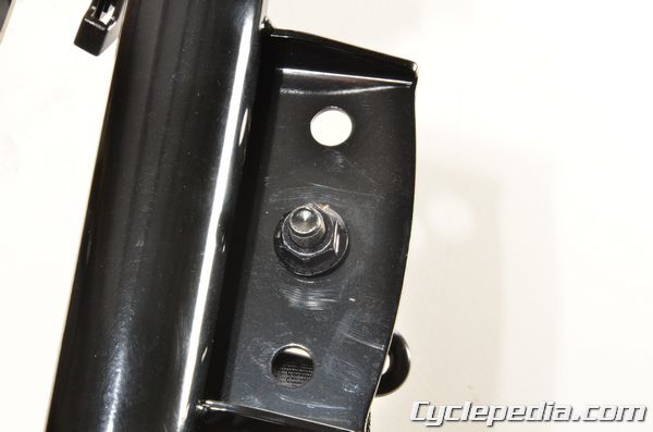
Loosen the nut with an 18 mm socket. Remove the nut, bolt, and washer. Free the upper seat belt from the canopy.
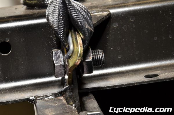
Hold the lower seat belt bolt with a 17 mm socket. Loosen the nut with an 18 mm socket. Remove the nut and bolt. Free the lower seat belt mount from the frame.
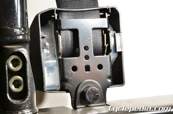
Remove the nut and bolt for the seat belt spool with a 17 and 18 mm socket. Remove the seat belt from the frame.
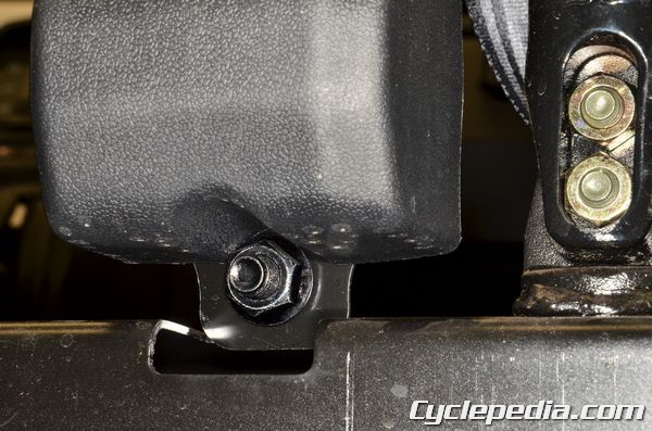
Use a 17 mm and 18 mm socket to remove the seat belt latch nut and bolt.
Install the seat belt components and tighten the nuts to specification.
Seat belt and frame: 5.9 kgf-m, (59 N-m, 42 ft-lb)
Install the upper seat belt cover.
Frame Covers / Skid Plates
SAFETY FIRST: Protective gloves and eyewear are recommended at this point.
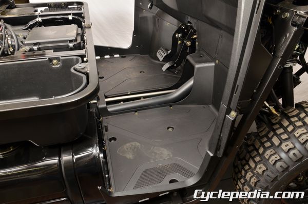
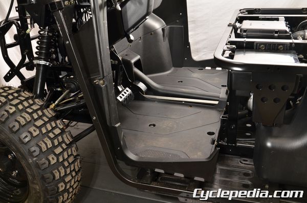
Under Seat Panel
Remove the seat and seat bracket. See the Seat topic for more information.
Remove the bolts and trim clips.
Remove the under seat panel.
Assembly is the reverse of disassembly.
Side Covers
Remove the following components
- Seat
- Front Mudguards – Front Fender
- Under Seat Panel
Remove the side cover bolts on the inside of the floor panel.
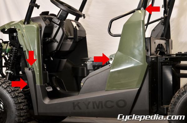
Remove the two trim clips from the front of the side cover, and the two bolts from the rear of the side cover.
Remove the three trim clips under the side cover.
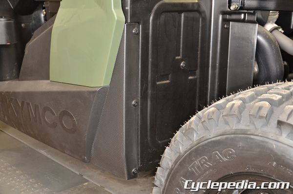
Remove the three trim clips from the rear of the side cover.
Remove the single trim clip that connects the side cover to the splash panel.
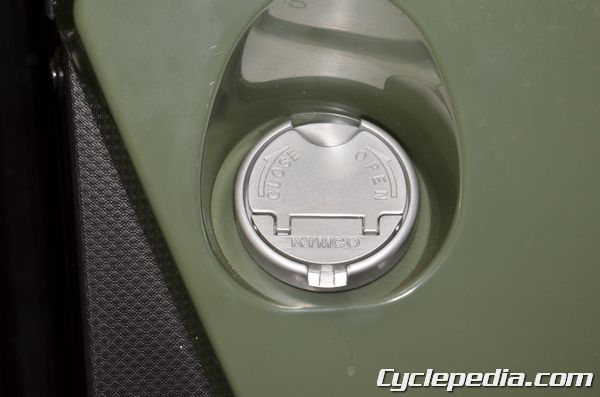
Temporarily remove the fuel tank cap to remove the tight side cover.
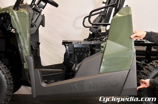
Remove the side cover.
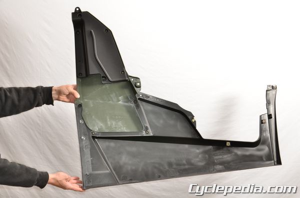
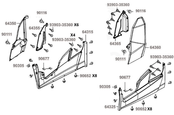
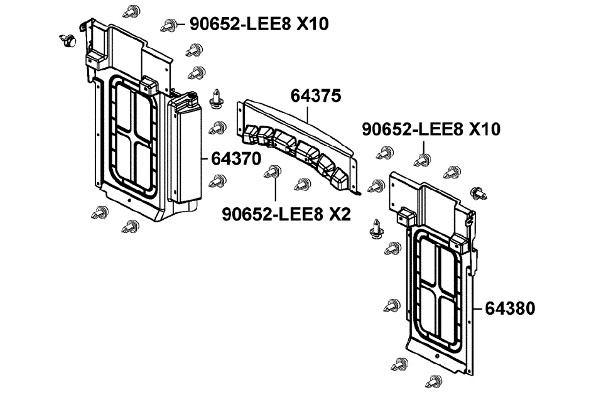
Disassemble the three parts of the side cover if needed.
Assembly is the reverse of disassembly.
Front Side Covers
Remove the following components:
- Seat
- Front Fender
- Under Seat Panel
- Side Covers
Remove the two bolts and trim clip from the outside of the front side cover.
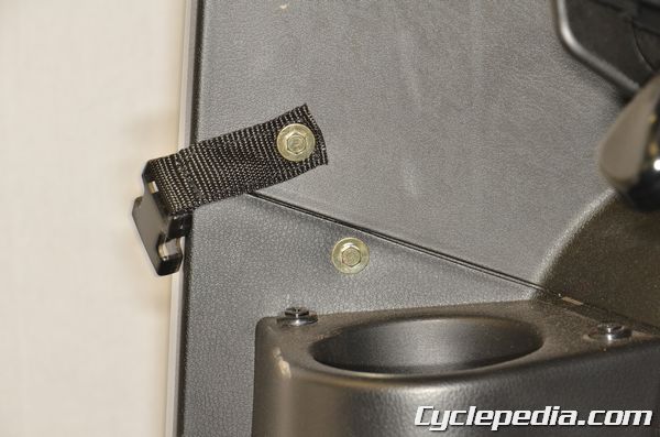
Remove the inside bolt with the net door latch.

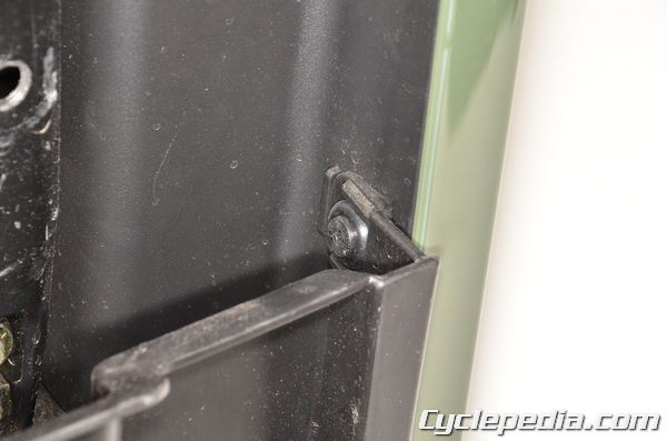
Free the front side cover tabs from the slots.
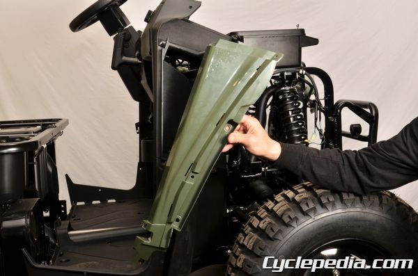
Remove the front side cover.
Assembly is the reverse of disassembly.
Splash Panels
Remove the following components:
- Seat
- Front Mudguards – Front Fender
- Under Seat Panel
- Side Covers
- Cargo Bed
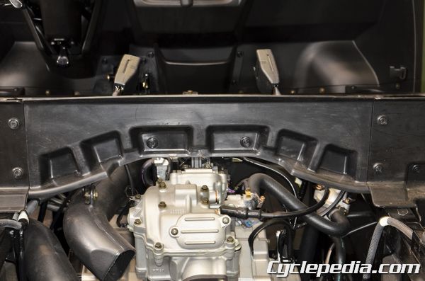
Remove the center splash panel trim clips.
Remove the center splash panel.
Remove the outer splash panel trim clips.
Remove the outer splash panels.
Assembly is the reverse of disassembly.
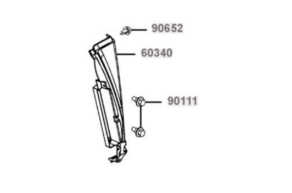
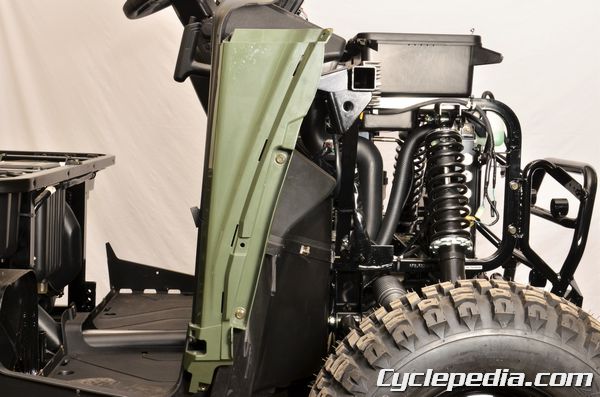
Front Left Inner Cover
Remove the trim clip.
Remove the front left inner cover.
To assemble, fit the front left inner cover into place on the frame and install the trim clip.
Skid Plates
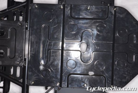
Remove the skid plate fasteners with a T30 Torx bit and remove the skid plates. To assemble, fit the skid plates into place and tighten the fasteners securely.
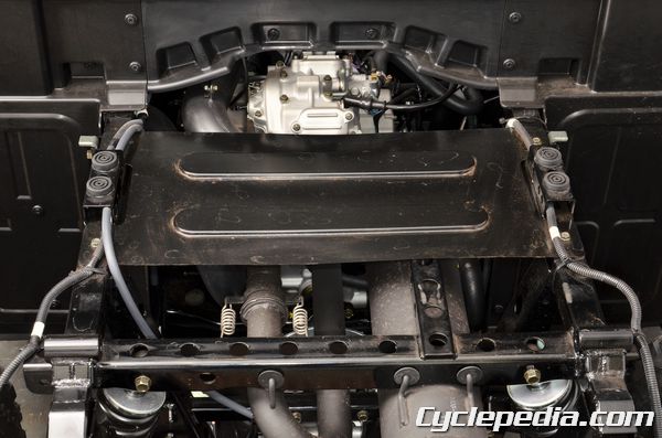
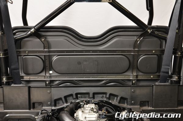
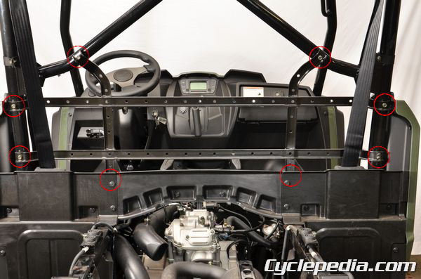
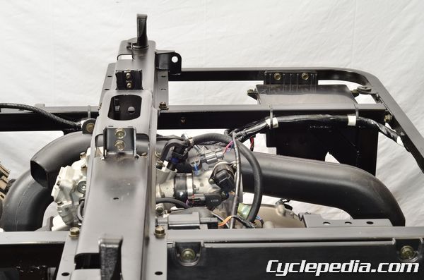
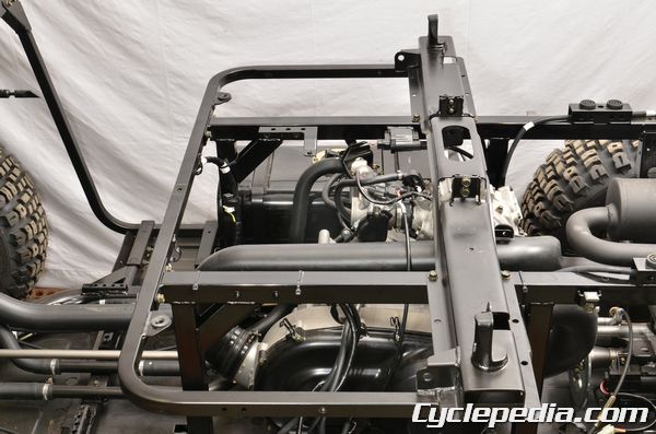
Seat Cross Pipe
SAFETY FIRST: Protective gloves and eyewear are recommended at this point.
Pull the lever and tilt back the cargo bed.
Remove the seat. See the Seat topic for more information.
Remove the rear frame covers, splash panels and under seat panel. See the Frame Covers topic for more information.
Remove the canopy. See the Canopy topic for more information.
Free the wire harness from the seat cross pipe. Note the routing for installation.
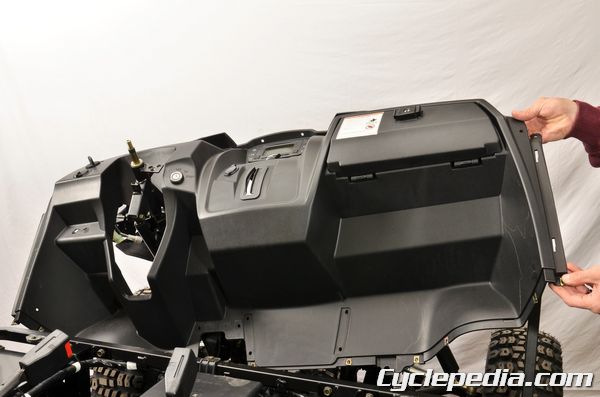
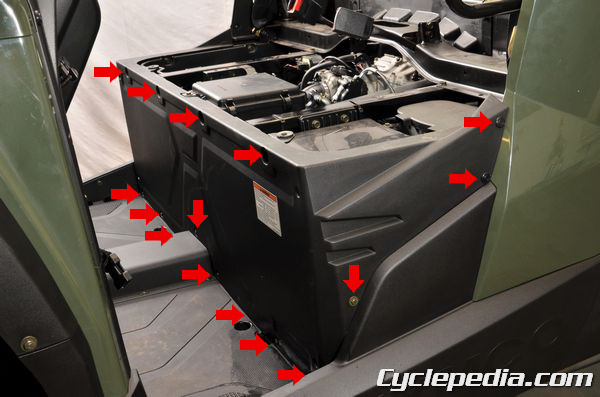
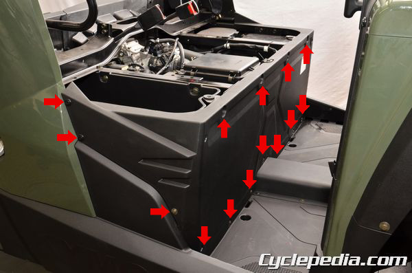
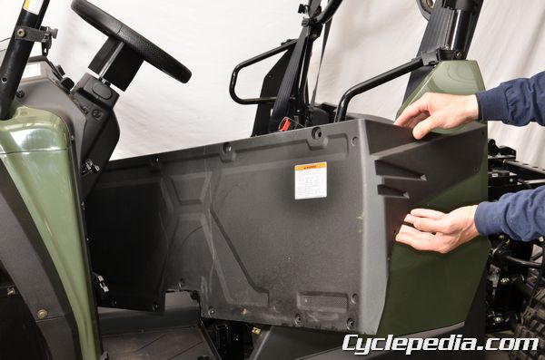
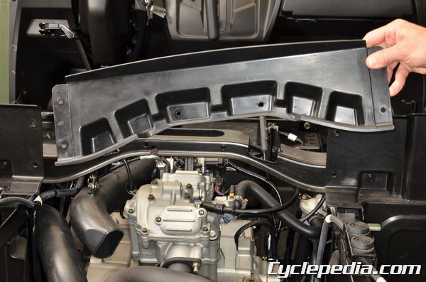
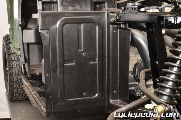
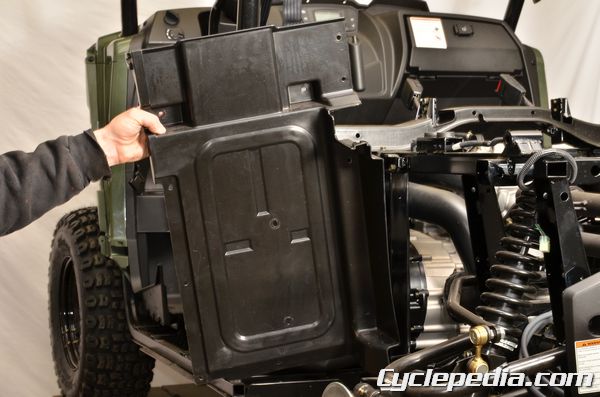
Remove the four right storage box bolts.
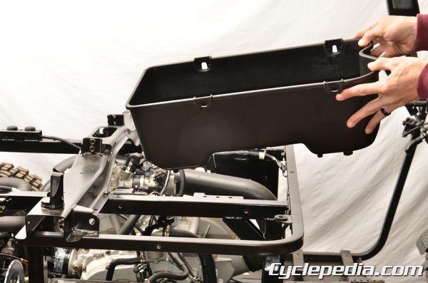
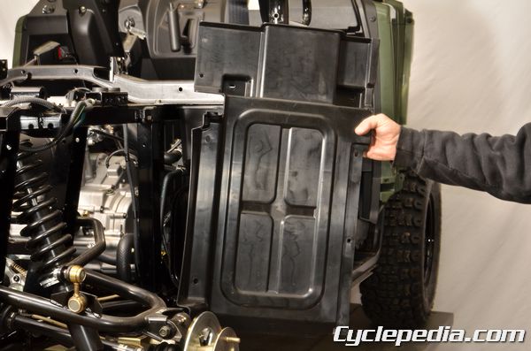
Remove the right storage box.
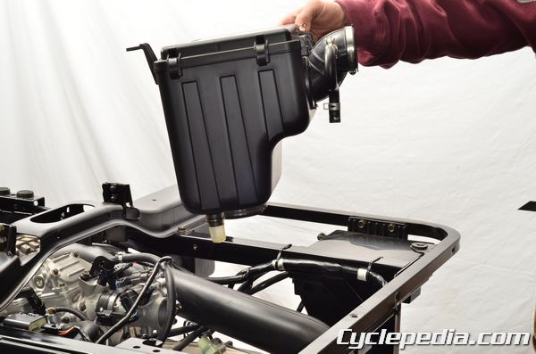
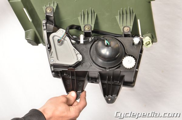
Remove the airbox. See the Airbox topic for more information.
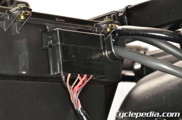
The fuse box is secured to the battery box. When it is installed it should click securely into place.
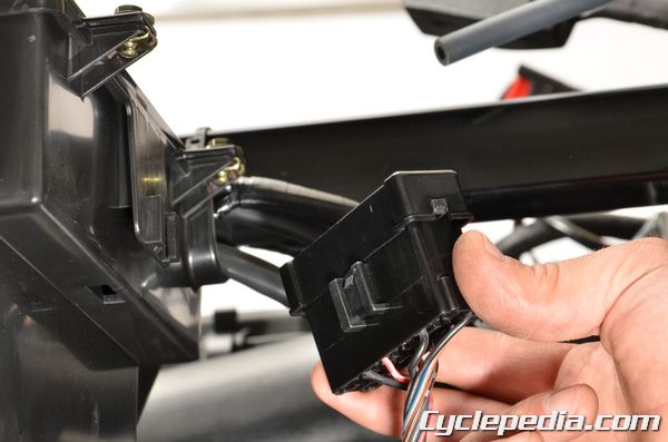
Free the fuse box from the back of the battery box.
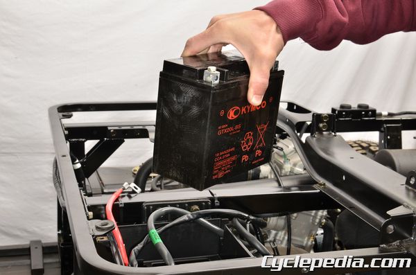
Remove the battery. See the Battery topic for more information.
The starter solenoid is secured in place by plastic mounts that fit into the rubber cover slots.
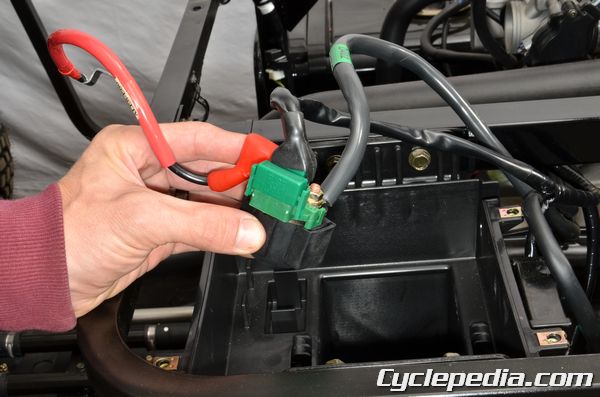
Lift the starter solenoid out of the battery box.
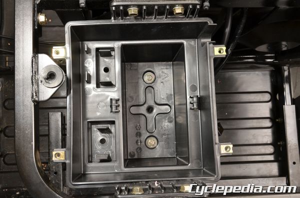
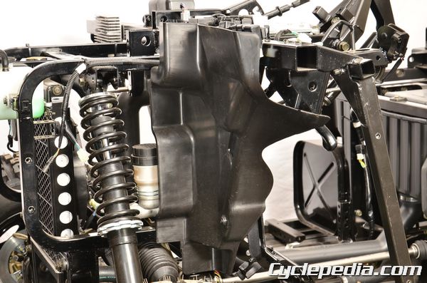
Remove the four battery box mounting bolts with a 12 mm socket.
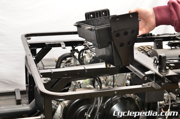
Remove the battery box.
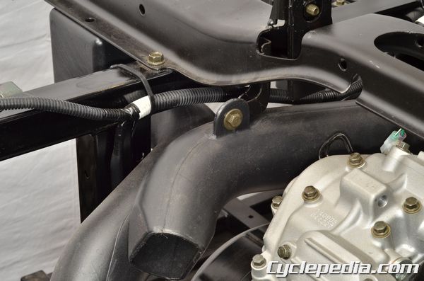
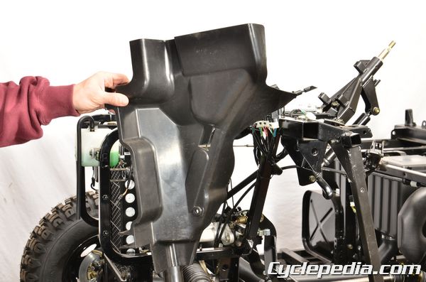
Remove the CVT duct bolt and nut with a 10 mm wrench.
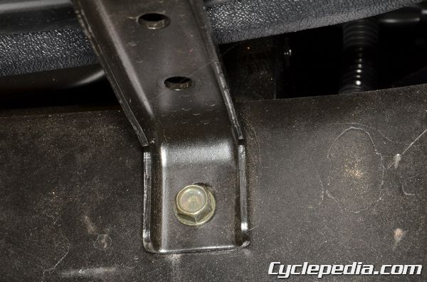
Remove the seat cross pipe mounting bolts with a 12 mm socket.
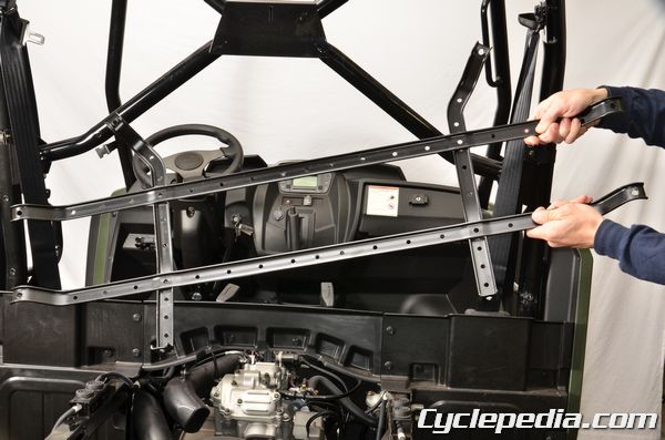
Remove the seat cross pipe from the frame.
Assembly is the reverse of disassembly.

Push the cargo bed down and lock it into place to complete assembly.
Front Bumper
SAFETY FIRST: Protective gloves and eyewear are recommended at this point.
Remove the following components:
- Hood
- Mudguards – Front Fender
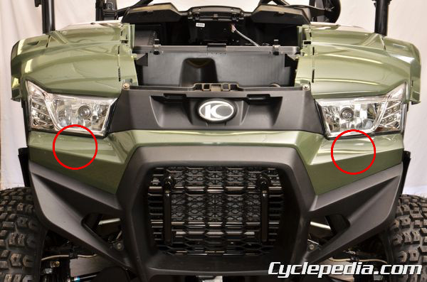
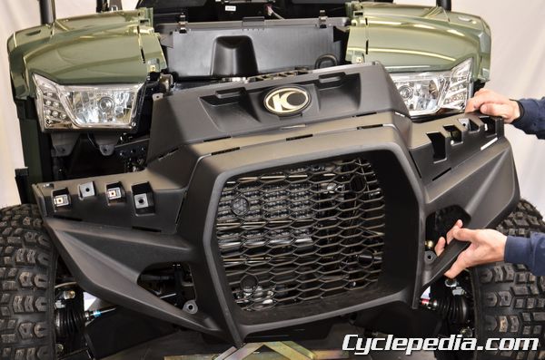
The front bumper trim panel has two trim clips.
Remove the trim clips.
Remove the front bumper trim panel.
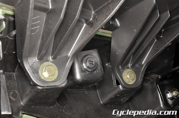
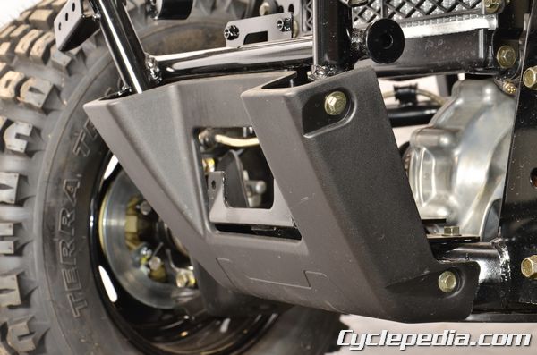
Remove the bumper holder bolts with a 12 mm socket.
Remove the bumper holders.
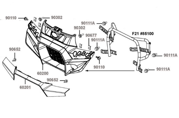

Remove the front bumper cover bolts.
Remove the front bumper cover.
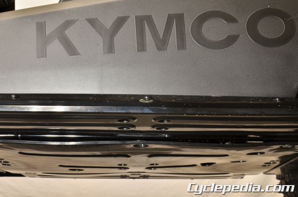
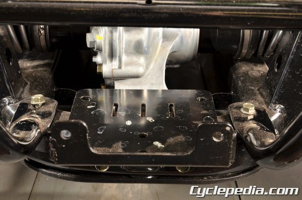
Remove the front skid plate bolts with a 10 mm socket.
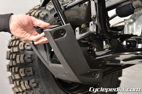
Remove the front skid plate.
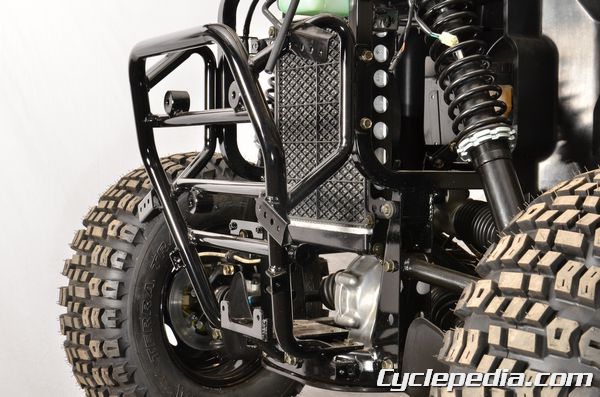
Remove the front bumper brace mounting bolts with a 12 mm socket.
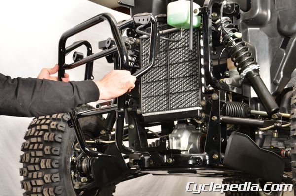
Remove the front bumper brace.
Assembly is the reverse of disassembly.
Front Fender
SAFETY FIRST: Protective gloves and eyewear are recommended at this point.
Trim Clips
- When removing frame covers, use special care not to pull them by force because the cover joint claws may be damaged.
- Make sure to route cables and harnesses according to the Cable & Harness Routing.
Screw Type
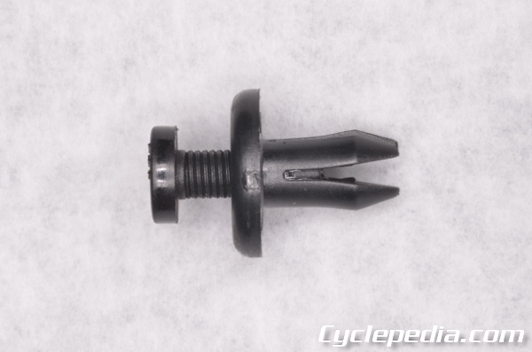
Back the screw out with a Phillips screwdriver to unlock the screw type trim clips. Install the trim clip and then turn in the screw to lock the clip in place.
Front Fender Mudguards
Remove the hood. See the Hood topic for more information.
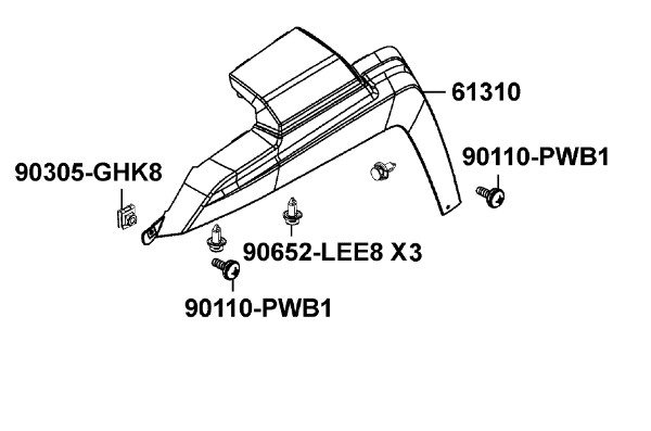
Note the location of the screws and trim clips.
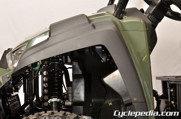
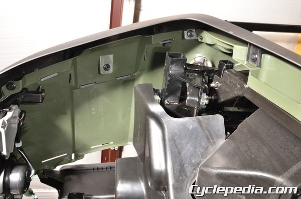
Remove the screws and trim clips.
Remove the mudguard.
Installation is the reverse of disassembly.
Top Panel Covers
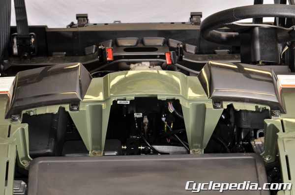
Each of the top covers are held in place with two trim clips.
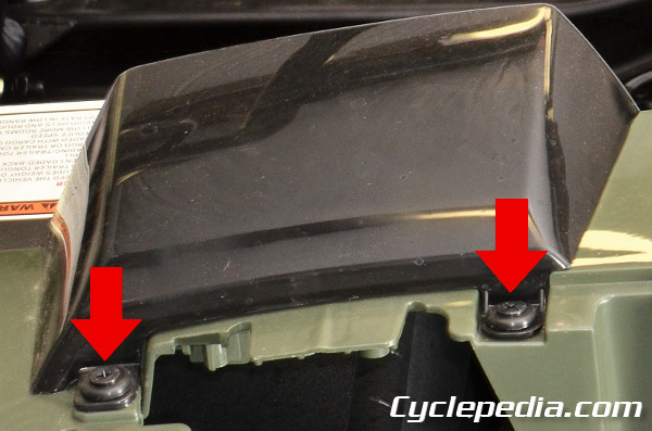
Remove the top cover trim clips.
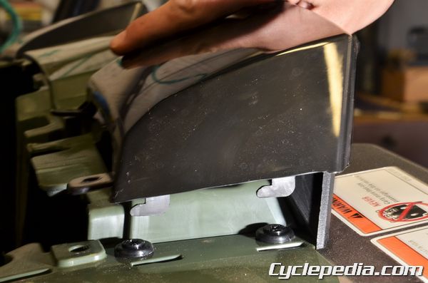
Free the top cover tabs from the slots.
Remove the top covers.
Remove the bolts and trim clips from the top panel cover.
Remove the two trim clips from above the meter.
Remove the top panel cover.
Installation is the reverse of disassembly.
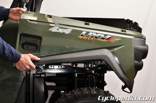
Front Fenders
Remove the front bumper. See the Front Bumper topic for more information.
Remove the canopy bars. See the Canopy topic for more information.
Remove the front fender bolts.
Remove the trim clips.
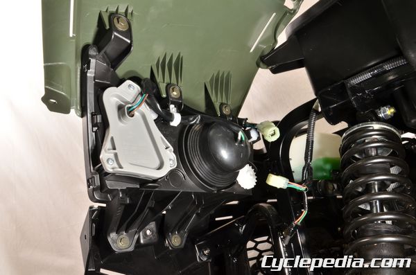
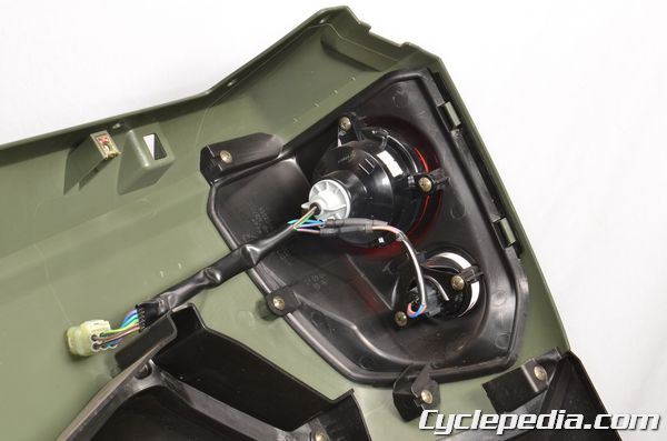
Unplug the headlight connectors.
Remove the front fenders with headlights.
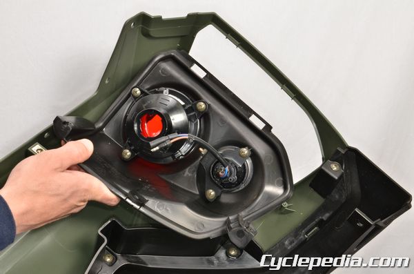
Remove the bolts to free the fender from the headlight.
Installation is the reverse of disassembly.
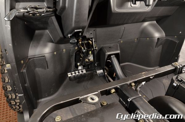
Floor Panel
SAFETY FIRST: Protective gloves and eyewear are recommended at this point.
Remove the following components:
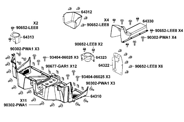
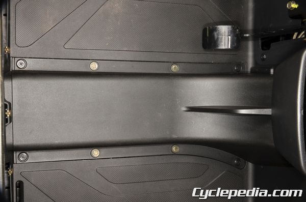
Remove the tunnel cover screws and trim clips.
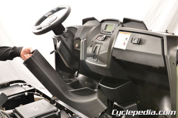
Remove the tunnel cover.
Remove the pedal plate trim clips. Remove the pedal plate.
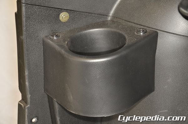
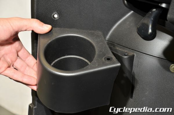
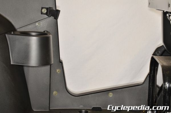
Remove the bolt and two trim clips with the cup holders. Remove the cup holders.
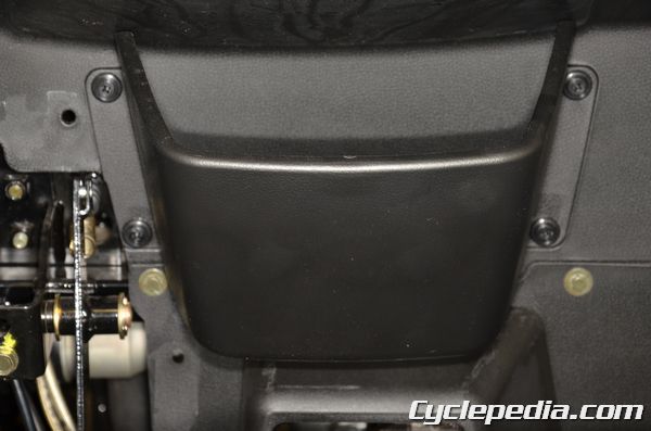
Remove the four glove holder trim clips. Remove the glove holder.
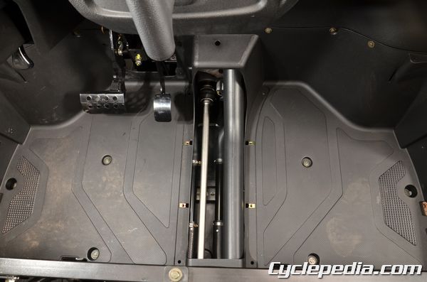
Remove the floor panel bolts.
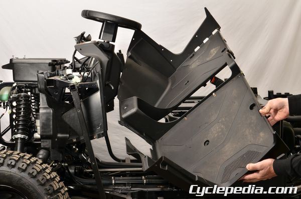
Remove the floor panel.
Assembly is the reverse of disassembly.
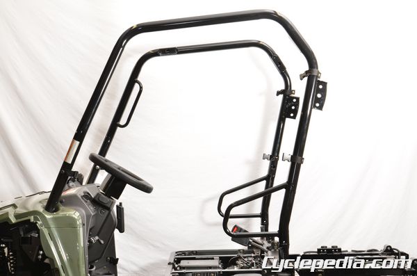
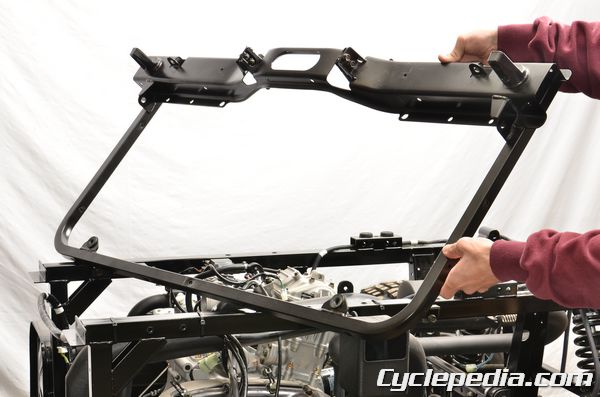
Canopy
SAFETY FIRST: Protective gloves and eyewear are recommended at this point.
Remove the following components:
- Seat, Seat Bracket, and Seat Belts – Seat
- Mudguards – Front Fender
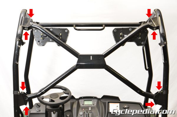
Rear the rear brace bolts with a 12 mm socket. Remove the rear brace.
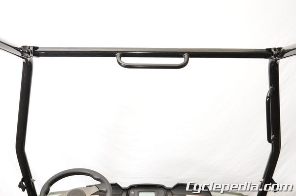
Remove the cross tube bolts with a 12 mm socket. Remove the cross tube.
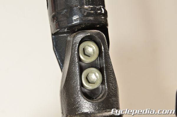
Loosen the rear canopy bar bolts with an 8 mm hex socket.
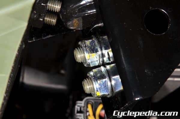
Hold the lower canopy bar nuts with a wrench and loosen the bolts with an 8 mm hex socket.
Remove the canopy bar nuts and bolts.
Remove the canopy bars.
Installation is the reverse of removal. Tighten the canopy bar bolts to specification with an 8 mm hex socket.
Canopy Bar Bolts: 6.4 kgf-m (64 Nm, 45 ft-lb)
Tighten the cross tube and rear brace bolts to specification with a 12 mm socket.
Cross Tube, Rear Brace Bolts: 3.2 kgf-m (32 Nm, 22.7 ft-lb)
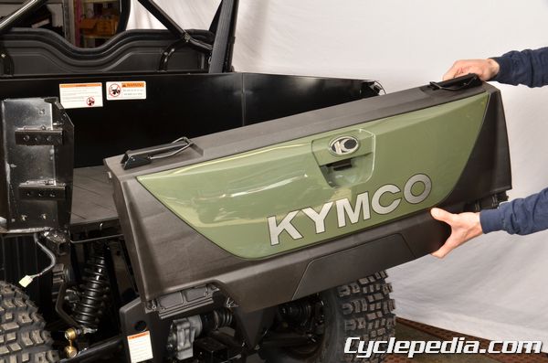
Cargo Bed
SAFETY FIRST: Protective gloves and eyewear are recommended at this point.
Operation
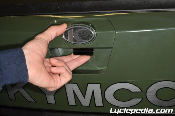
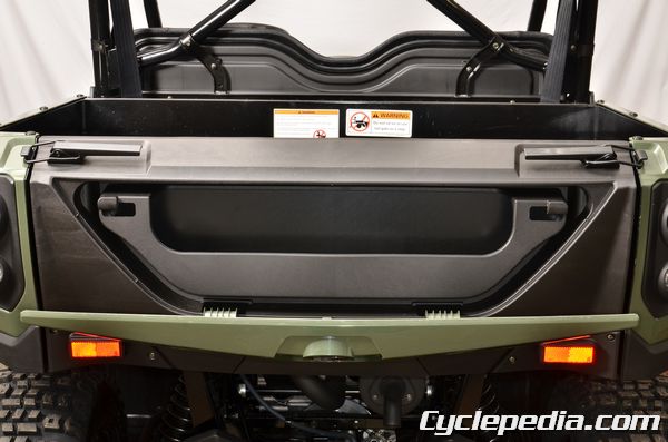
Use the latch to open the tailgate storage compartment.
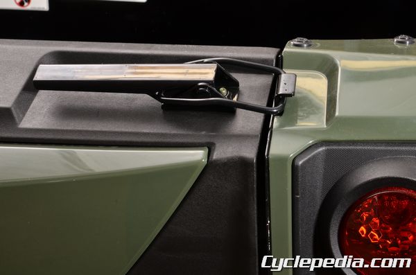
Use the latch levers to open and close the tailgate.
Use the latch to unlock and lift the cargo bed.
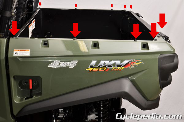
Cargo Bed
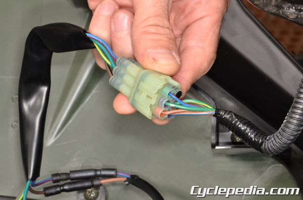
Unplug the taillight connectors. There is one for each side.
Free the taillight wires from the cargo bed.
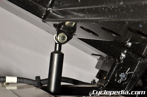
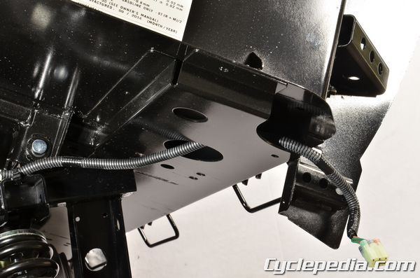
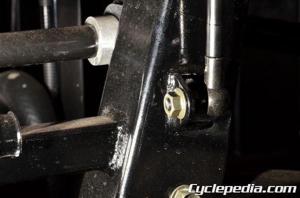
Hold the lift assist strut with a 12 mm wrench and remove the nuts with a 12 mm socket. Free the left and right lift assist struts from the bed.
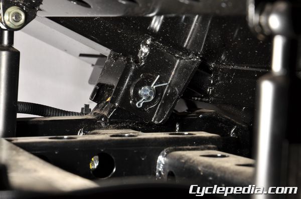
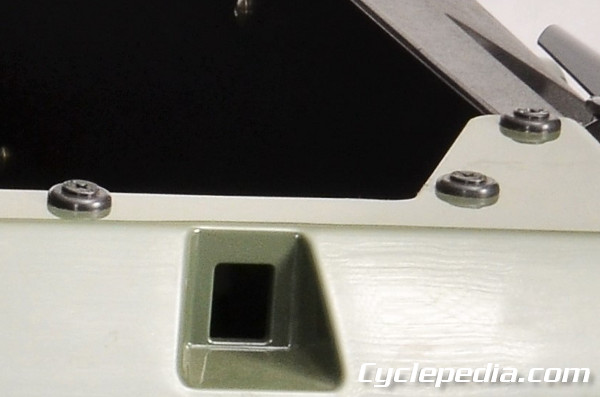
With the help of an assistant support the bed in the closed position. Remove the locking clips.
Slide out the hinge pins.
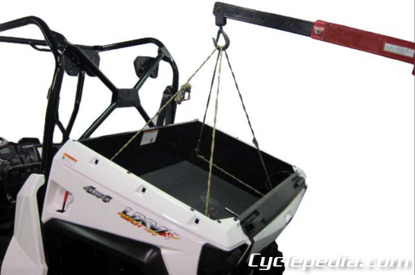
Lift off the bed with the help of an assistant or use a suitable hoist.
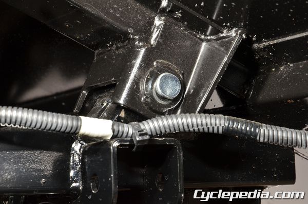
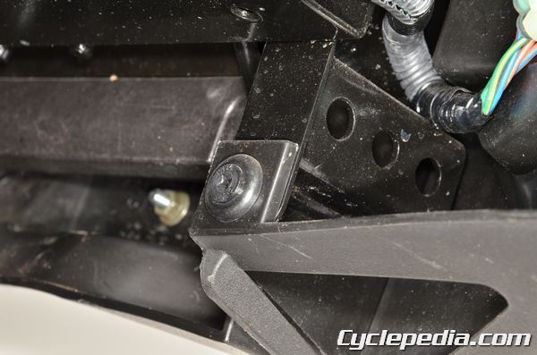
Remove the lower nuts to remove the assist struts from the frame if necessary.
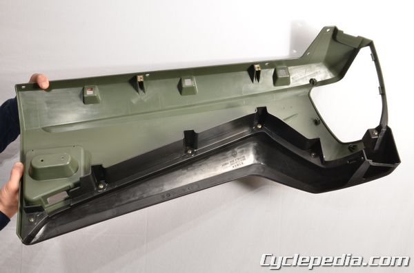
Inspect the rubber bumpers for damage and deterioration. Remove the two bolts on each side to remove the heat shield if needed.
Assembly is the reverse of disassembly.
Tailgate
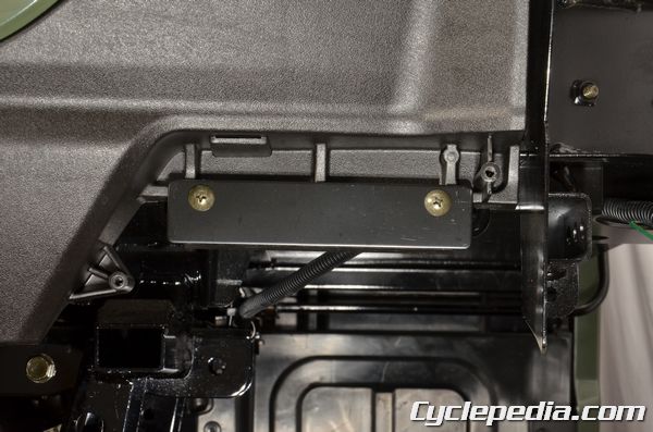
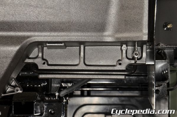
To remove the tail gate plate, remove the screws with a Phillips screwdriver.
Remove the tail gate plate if necessary.
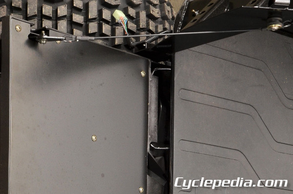
Remove the cable bolts and remove the cables from the tailgate.
Remove the two pivot covers screws with a Phillips screwdriver. Remove the pivot cover from each side of the tailgate.
Remove the pivot plate screws with a Phillips screwdriver.
Remove the pivot plates.
Remove the tailgate.
Assembly is the reverse of disassembly.
Rear Fender
SAFETY FIRST: Protective gloves and eyewear are recommended at this point.
Trim Clips
- When removing frame covers, use special care not to pull them by force because the cover joint claws may be damaged.
- Make sure to route cables and harnesses according to the Cable & Harness Routing.
Screw Type
Back the screw out with a Phillips screwdriver to unlock the screw type trim clips. Install the trim clip and then turn in the screw to lock the clip in place.
Rear Fender Removal
Remove the trim clips from the top of the fender.
Remove the trim clip under the fender.
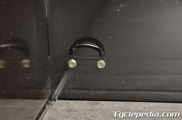
Hold the front tie-down ring bolts with a wrench.
Loosen the cap nuts with a 10 mm socket. Remove the cap nuts and front tie-down rings and bolts.
Unplug the taillight connector.
Remove the fender.
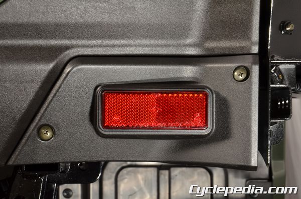
Remove the taillight screws with a #2 Phillips screwdriver to remove the taillight from the rear fender.
Free the taillight assembly from the tabs on the rear fender and removed it.
Remove the screws with a #2 Phillips screwdriver to remove the molding from the bottom of the fender.
Installation is the reverse of disassembly.
Exhaust System
SAFETY FIRST: Protective gloves and eyewear are recommended at this point.
WARNING: Exhaust systems reach a very hot temperature after the vehicle has been running. Wait for the exhaust system to cool down to prevent severe burns.
Always replace the exhaust gaskets when removing and installing the exhaust system to prevent an exhaust leak.
Removal
Remove the cargo bed. See the Cargo Bed topic for more information.
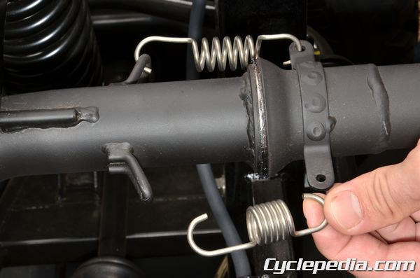
Use a spring puller to free the exhaust springs from the head pipe.
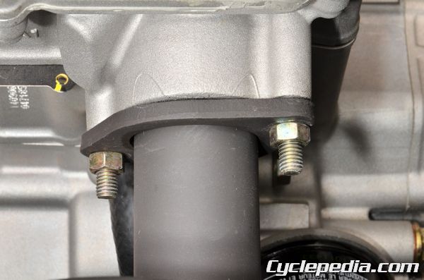
Remove the head pipe nuts with a 12 mm socket.
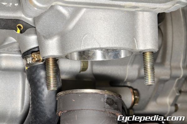
Slide the head pipe back to free it from the head and muffler.
Remove the head pipe from the vehicle.
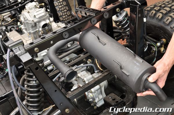
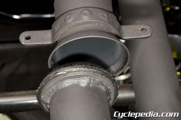
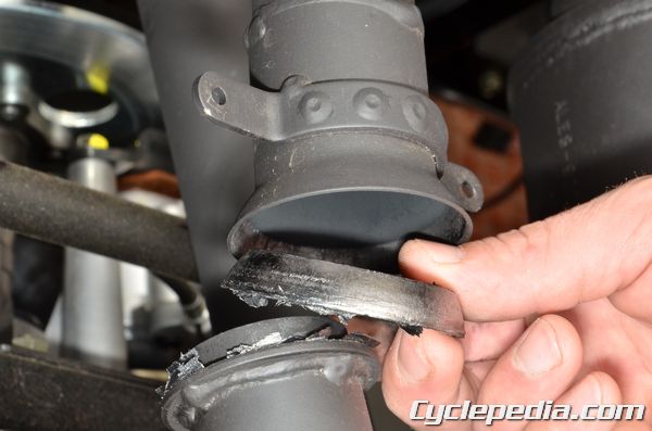
Slide the muffler back to free the hangers from the rubber grommets, remove the muffler from the vehicle.
Installation
Check that the rubber grommets are in good condition, fit the muffler hangers into the grommets.
Fit the new exhaust gaskets into place. Align the head pipe with the cylinder head and muffler while installing the head pipe.
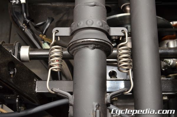
Use a spring puller to install the exhaust springs, make sure the springs are securely locked into place.
Tighten the head pipe nuts evenly a little at a time until you reach the tightening specification.
Head Pipe Nut Torque: 2.0 kgf-m (20 N-m, 15 ft-lb)
Install the cargo bed. See the Cargo Bed topic for more information.
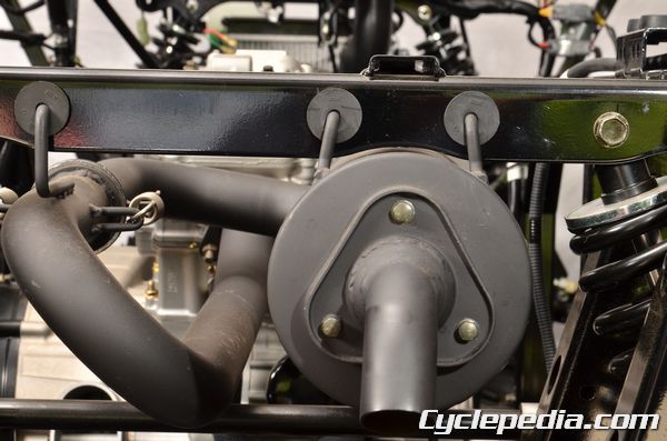
Spark Arrestor
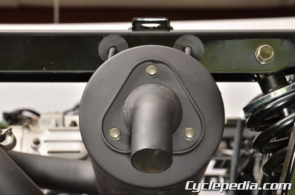
Remove the three spark arrestor bolts with an 8 mm socket.
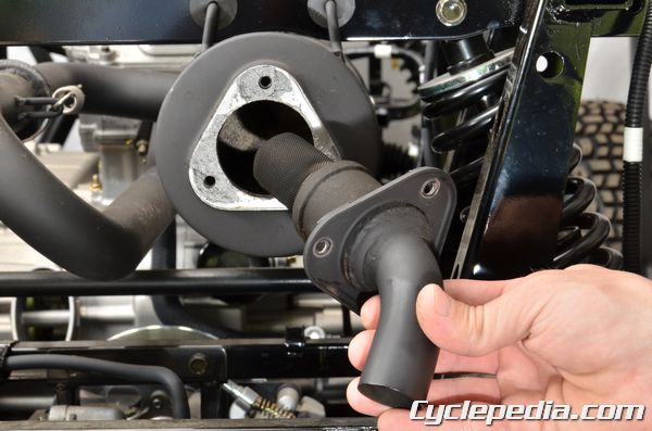
Remove the spark arrestor and gasket.
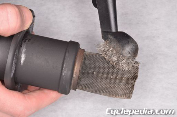
Clean the carbon off of the spark arrestor screen with a wire brush. Inspect the spark arrestor screen for any damage and replace as needed.
Install the spark arrestor with a new gasket. Install the spark arrestor bolts and tighten them securely with an 8 mm socket.
Spark Arrestor: 5.4 Nm, 0.54 kgf-m, 48 in-lb
Shifter
SAFETY FIRST: Protective gloves and eyewear are recommended at this point.
Handle
Remove the two shifter handle screws with a #2 Phillips screwdriver.
Remove the shifter handle.
To reinstall, fit the handle into place and tighten the screws securely.
Adjustment
Note: Improper shifter adjustment can cause transmission damage.
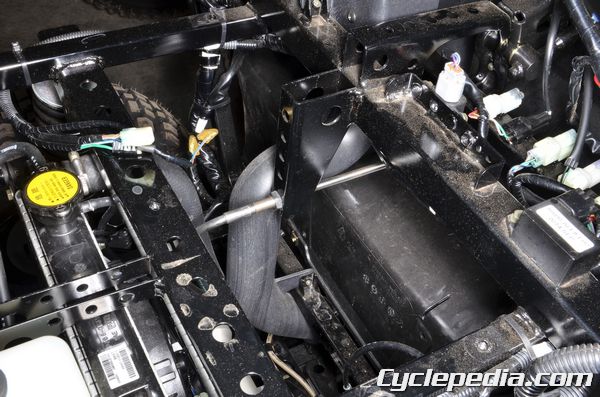
Remove the under seat panel to gain access to the lower cable adjustment.
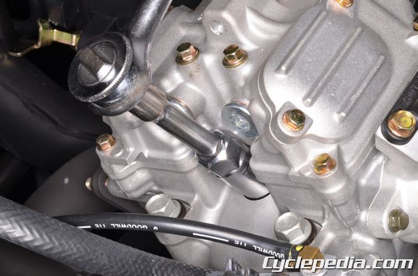
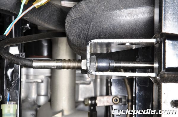
Loosen the lock nuts with a 17 mm wrench and move the cable in or out to change the engagement position of the shifter.
Check the shifter position as you adjust the cable, make sure the shifter allows the transmission to fully engage each position and that it is properly indicated on the display meter. Tighten the lock nuts securely when finished adjusting.
Cable Removal
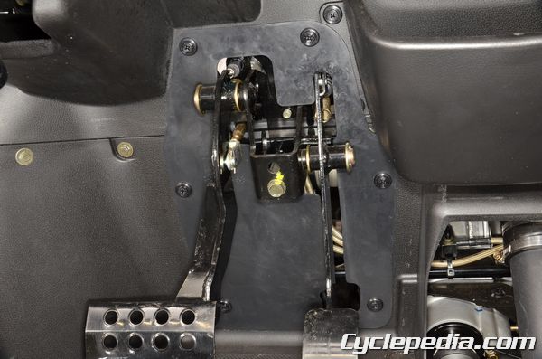
Remove the instrument cover. See the Instrument Cover topic for more information.
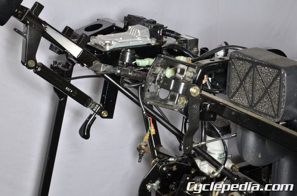
Remove the mounting bolts with a 12 mm socket to free the shifter assembly from the frame.
Loosen the lock nuts with a 17 mm socket to free the cable from the upper mounting bracket.
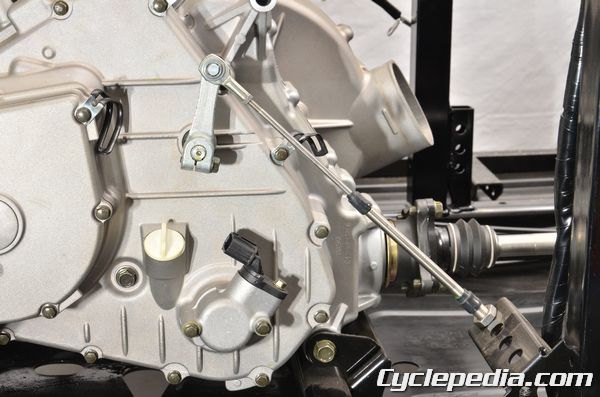
Remove the pinch bolt from the shift linkage with a 10 mm socket and free the shift linkage from the shift shaft.
Loosen the lock nuts with a 17 mm socket and remove the lower portion of the cable from the mounting bracket.
Installation
Fit the upper and lower portion of the cable adjusters into the mounting brackets.
Fit the gear shift linkage into place while aligning the punch marks on the shaft and arm. Tighten the pinch bolt securely.
Mount the shifter assembly onto the frame and tighten the mounting bolts securely.
Install the instrument cover. See the Instrument Cover topic for more information.
Adjust the gear shifter position as describe in this chapter and tighten the lock nuts securely.
Cooling System Inspection
SAFETY FIRST: Antifreeze is highly toxic and can kill pets and animals if drank. Do not leave coolant where animals (including children) can get to it. Protective gloves and eyewear are recommended at this point.
CAUTION: Never remove the radiator cap when the engine is hot.
- Perform this operation when the engine is cold.
- To inspect the coolant level see the Coolant topic.
Pressure Testing
Remove the hood. See the Hood topic for more information.
Remove the radiator cap in two stages so that any built up pressure can vent before you remove it. Remove the radiator cap by pushing down and turning it.
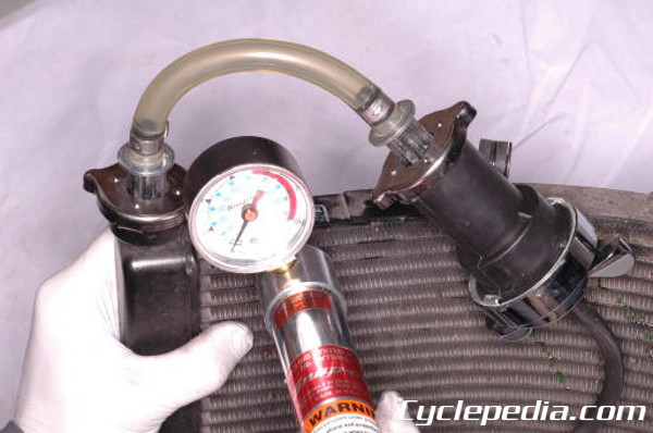
When checking the cooling system for leaks you will need a pressure tester. Remove the radiator cap, wet the tester seal, and install the end of the pressure tester onto the filler neck. Pump the tester up until the gauge reads 0.9 kg/cm2 or 12.8 psi. The cooling system should hold this pressure for at least 6 seconds. If it does not you will need to inspect the entire system for leaks. Do not pressurize the cooling system more than 1.05 kg/cm2 or 14.9 psi.
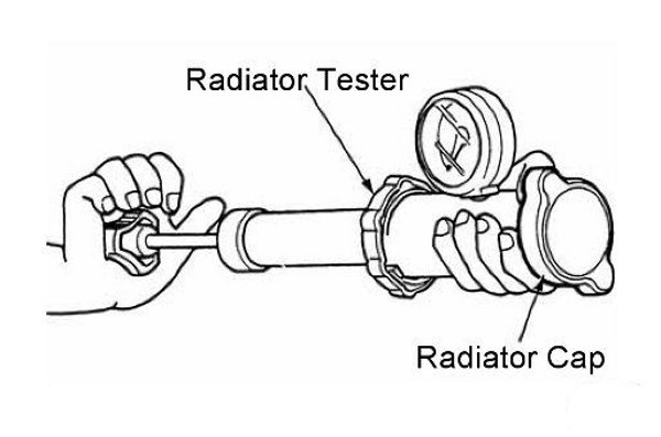
Wet the seal on the radiator cap and install it to the pressure tester. Replace the cap if it does not relieve the pressure as specified.
Radiator cap relief pressure: 90 kPa (0.9 kgf/cm2, 12.8 psi)
Reinstall the radiator cap.
Radiator
SAFETY FIRST: Antifreeze is highly toxic and can kill pets and animals if drank. Do not leave coolant where animals (including children) can get to it. Protective gloves and eyewear are recommended at this point.
CAUTION: Never remove the radiator cap when the engine is hot.
Radiator Removal
Remove the following components:
Remove the two radiator reservoir mounting bolts with a 10 mm socket. Remove the reservoir tank.
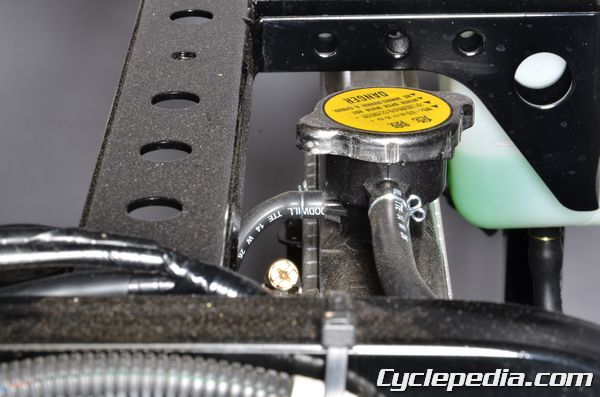
Squeeze and slide back the clamps on the siphon and air bleed hoses using a pair of pliers. Free the siphon hose from the side of the filler neck and the air bleed hose from the back of the filler neck.
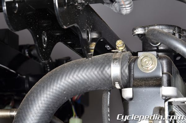
Loosen the upper radiator hose clamp with a #2 screwdriver. Free the upper coolant hose from the radiator.
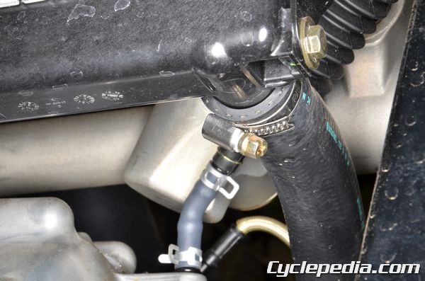
Loosen the lower radiator hose clamp with a #2 screwdriver. Free the lower coolant hose from the radiator.
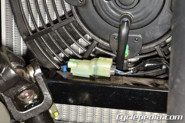
Unplug the radiator fan connector.
Free the cable secured by the stay on the radiator fan mount.
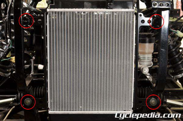
If the radiator grill needs to be removed, loosen and remove the four radiator grill bolts using a 10 mm socket.
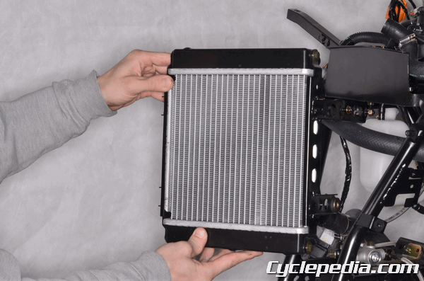
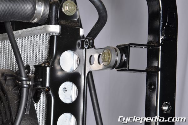
Remove the radiator from the frame. Inspect the rubber grommets and replaced them if they are in poor condition.
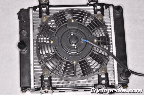
To remove the fan take off the four mounting nuts with a 10 mm socket.
Radiator Inspection
Radiator Fins
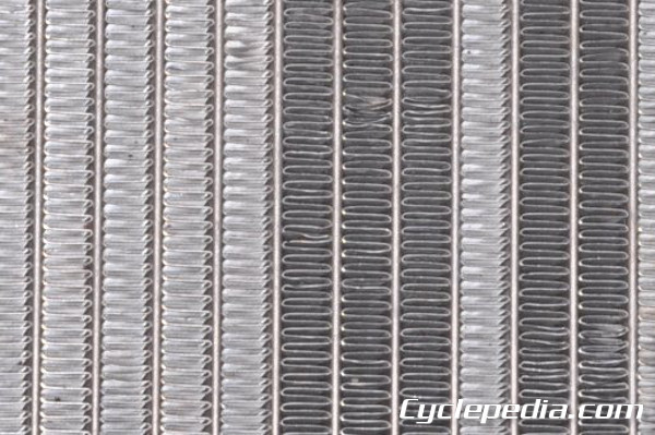
Inspect the radiator fins for damage and clogging. Clean out the fins with low pressure compressed air and water.
NOTE: Always wear safety glasses when using compressed air and never point it directly at yourself or anyone else.
Check the radiator for any bent or damaged fins. Use a small flat blade screwdriver to straighten them out, but be careful not to puncture the radiator.
Radiator Fan Testing
Jump a 12 volt battery to the fan connector and make sure the radiator fan operates.
To inspect the water temperature sensor (WTS) see the FI Sensors topic.
Radiator Installation
If the radiator fan was removed, reinstall the fan and tighten the four nuts securely with a 10 mm socket.
Fit the radiator into place.
Install the four radiator mounting bolts and tighten them securely with a 10 mm socket. Secure the cable with the stay on the radiator fan mount.
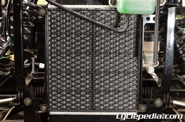
Install the radiator grill and tighten the bolts securely with a 10 mm socket.
Plug in the radiator fan connector.
Connect the lower coolant hose to the radiator. Install the clamp and tighten it securely with a #2 Phillips screwdriver.
Connect the upper coolant hose to the radiator. Install the clamp and tighten its securely with a #2 Phillips screwdriver.
Connect the siphon hose to the side of the filler neck and the air bleed hose to the back of the filler neck. Secure the hoses with the clamps.
Install the reservoir tank. Install the two mounting bolts and tighten them securely with a 10 mm socket.
Install the following components:
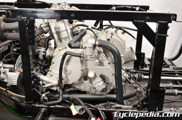
Water Pump
SAFETY FIRST: Antifreeze is highly toxic and can kill pets and animals if drank. Do not leave coolant where animals (including children) can get to it. Protective gloves and eyewear are recommended at this point.
Water Pump Inspection
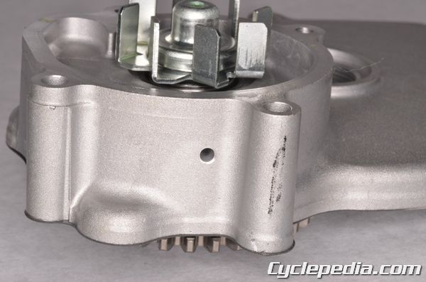
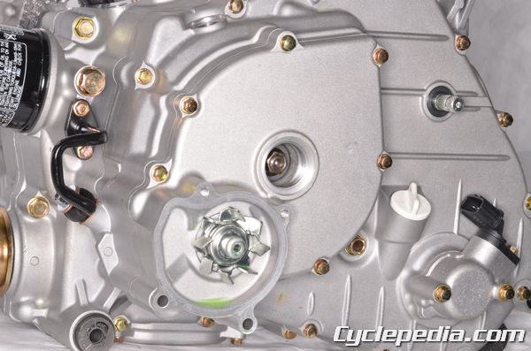
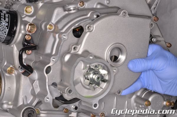
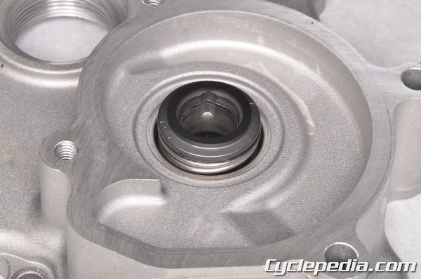
Inspect the telltale hole at the bottom of the water pump for signs of coolant. If coolant is detected then the mechanical seal must be replaced.
Water Pump Removal
Remove the following components:
Impeller Housing
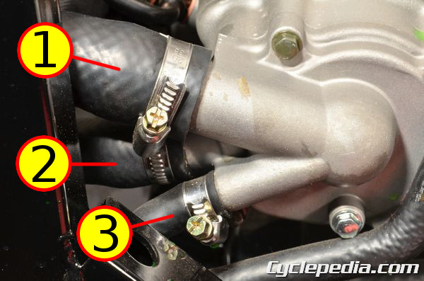
Loosen the coolant hose clamps with a #2 Phillips screwdriver.
- Radiator
- Cylinder
- Thermostat
Free the coolant hoses from the water pump.
The impeller cover is held in place by four bolts.
Remove the four impeller cover bolts with an 8 mm socket.
Remove the impeller cover.
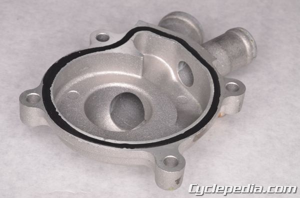
Remove the impeller cover O-ring and discard it.
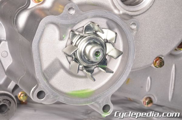
Inspect the impeller for damage.
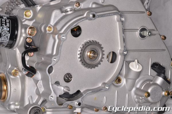
Water Pump Cover
Loosen the water pump cover bolts in a crisscross pattern with an 8 mm socket.
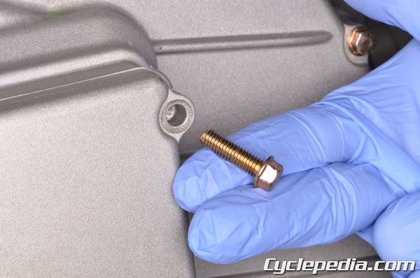
Remove the water pump cover bolts.
Remove the water pump cover and old gasket.
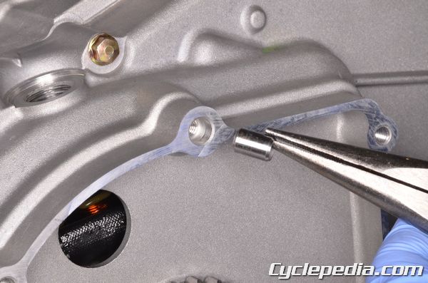
Remove the two water pump cover dowel pins. Remove any remaining gasket material from the mating surfaces.
Water Pump Seal Replacement
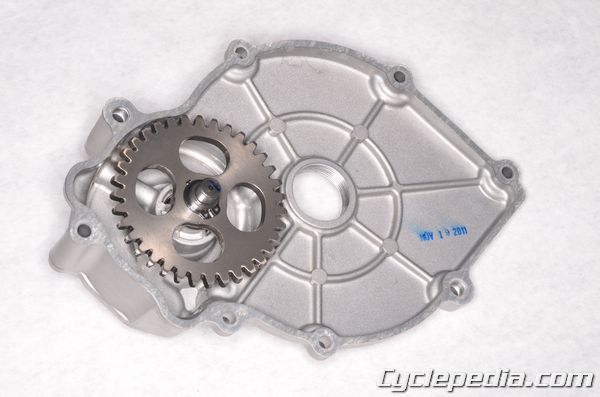
The water pump driven gear must be removed to access the water pump seal.
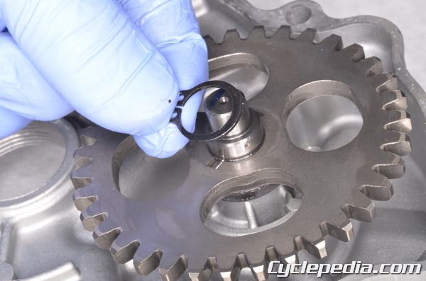
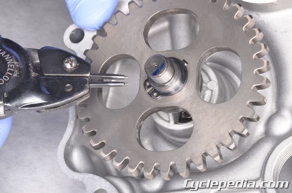
Remove the water pump driven gear snap ring with snap ring pliers.
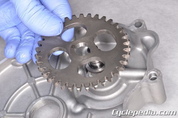
Lift off the water pump driven gear.
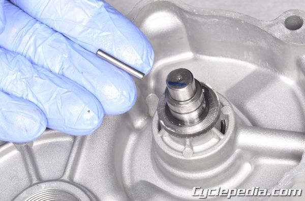
Remove the water pump driven gear pin.
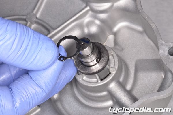
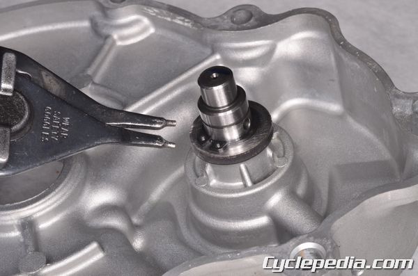
Remove the water pump snap ring with snap ring pliers.
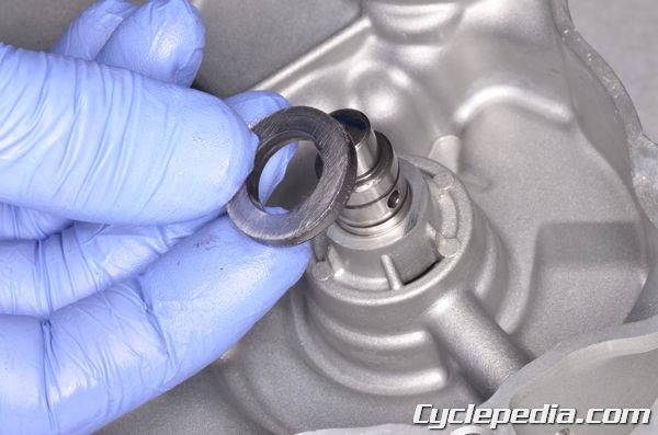
Lift off the washer.
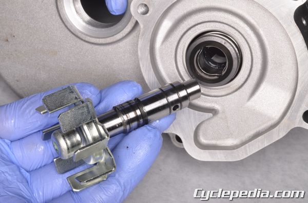
Slide out the water pump impeller.
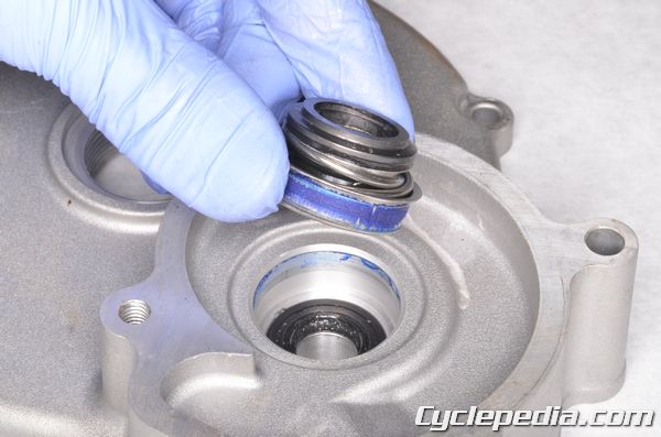
Remove the mechanical seal from the water pump cover. If the mechanical seal is difficult to remove you can tap the tip of a small sheet metal screw into the inner-metal edge of the seal. Grip the screw with a pair of vise-grip pliers and pull the seal out.
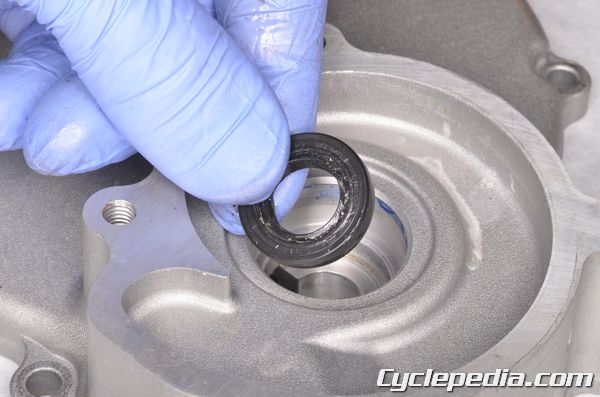
Remove the oil seal.
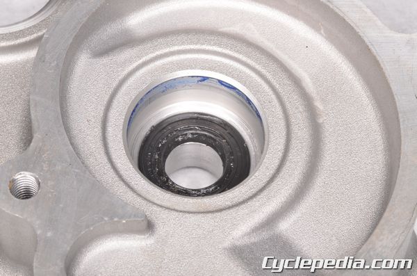
Lubricate the lips of the new oil seal with grease. Drive the new oil seal into place using a suitable driver that is the same outside diameter as the seal. Apply coolant to the new mechanical seal.
Drive the new mechanical seal into place using a suitable driver that is the same outside diameter as the seal. Make sure the seal is fully seated.
Install the impeller.
Place the washer on the impeller shaft.
Install a new snap ring into the groove with snap ring pliers.
Install the pin into the impeller shaft.
Install the water pump driven gear onto the impeller shaft. Secure the water pump driven gear with a new snap ring. Make sure the snap ring fits securely into the groove.
Water Pump Installation
Water Pump Cover
Make sure the water pump cover mating surface is clean.
Install the two water pump cover dowel pins and a new gasket.
Install the water pump cover. Insert the bolts and tighten the evenly to specification in a crisscross pattern with an 8 mm socket.
Water Pump Cover: 10 Nm, 1 kgf-m, 10 ft-lb
Impeller Housing
Place a new O-ring on the impeller housing. Apply coolant to the new O-ring.
Fit the impeller housing into place. Install the four impeller cover bolts and tighten them securely with an 8 mm socket.
Connect the coolant hoses to the water pump. Tighten the clamps securely with a #2 Phillips screwdriver.
- Radiator
- Cylinder
- Thermostat
Install the following components:
Thermostat
SAFETY FIRST: Antifreeze is highly toxic and can kill pets and animals if drank. Do not leave coolant where animals (including children) can get to it. Protective gloves and eyewear are recommended at this point.
Thermostat Removal
Remove the following components:
The thermostat is located on the right side of the engine.
- Cylinder Head
- Radiator
- Water Pump
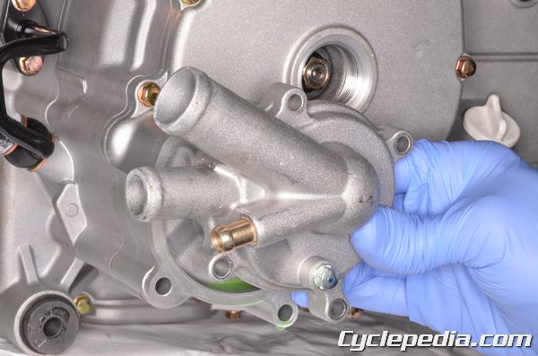
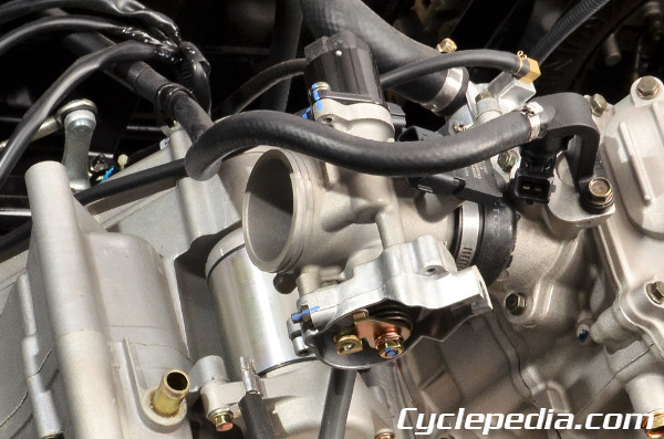
It is not necessary to disconnect the hoses to replace the thermostat. However, if you need to remove the thermostat housing from the vehicle then you will want to loosen the coolant hose clamps with a #2 Phillips screwdriver. Remove the hoses from the thermostat housing.
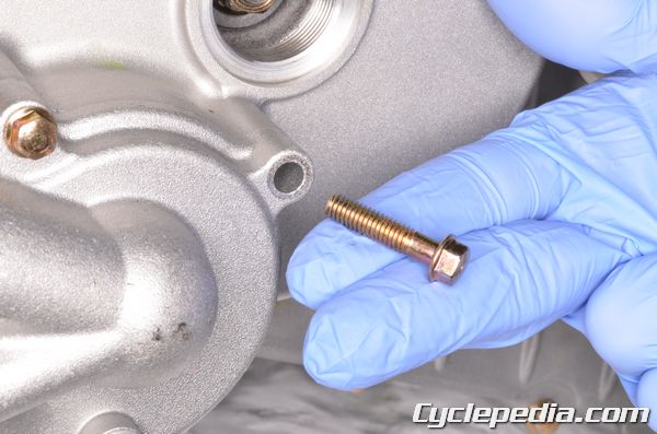
Remove the two thermostat housing bolts with an 8 mm socket.
Separate the housing cover from the thermostat housing.
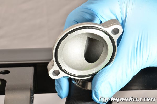
Remove the O-ring from the housing cover.
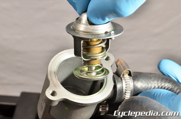
Remove the thermostat.
Thermostat Inspection
Inspect the thermostat at room temperature. If the valve is open the thermostat is defective and needs to be replaced. Inspect the thermostat sealing ring – replace the thermostat if it’s in poor condition. To check the thermostat for proper operation, fill a pan with tap water and suspend the thermostat in it with a piece of wire. The thermostat should be completely immersed in water and should not touch any part of the pan. Place the pan on a burner and heat the water. Gently stir the water and put a thermometer in the pan. When the thermostat starts to open note the reading on the thermometer. Carefully remove the thermostat from the heated water. The thermostat should close once it cools to room temperature.
Valve Starting to Open: 80 – 84 degrees C (176 – 183 degrees F)
Valve Fully Open: 95 degrees C (203 degrees F)
Valve Lift: 8 mm (0.3 in) minimum
Thermostat Installation
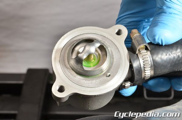
Install the thermostat so its air bleed hole faces up and aligns with the tab in the housing.
Install a new O-ring in the housing cover.
Join the housing cover with the thermostat housing. Install the thermostat housing bolts and tighten them securely with an 8 mm socket.
If the thermostat housing was removed then you will want to reconnect the hoses at this point. Tighten the hose clamps securely.
- Cylinder Head
- Radiator
- Water Pump
Install the following components:
Fuel System
WARNING
Gasoline is very dangerous. When working with gasoline, keep sparks and flames away from the working area.
Gasoline is extremely flammable and is explosive under certain conditions. Be sure to work in a well-ventilated area.
General Service Information
● Be sure to relieve the fuel pressure before fuel pump or fuel hose removal.
● Bending or twisting the control cables will affect operation and could cause the cables to stick or bind, resulting in loss of vehicle control.
● Work in a fully ventilated area. Smoking or allowing flames or sparks in the work area or where gasoline is stored can cause a fire or explosion.
● Do not apply carburetor cleaners to the inside of the throttle body.
● Do not snap the throttle valve from fully open to fully close after the throttle cable has been removed; this may cause incorrect idle speed.
● Do not loosen or tighten the painted bolts and screws of the throttle body. This can cause throttle and idle valve synchronization failure.
● Seal the cylinder head intake ports with tape or a clean towel to prevent dirt and debris from entering the intake ports after the throttle body has been removed.
● Do not damage the throttle body. It may cause incorrect throttle and idle valve synchronization.
● When the fuel pump is removed make sure it is stored in a clean area where it cannot fall and be damaged. Also, be sure the fuel pump isn’t resting on the fuel level sensor float arm.
● Always replace the fuel pump seal when the fuel pump is removed.
● The electronic fuel injection system is equipped with the self-diagnostic system. If the Check Engine Lamp “CELP” lights while riding, follow the self-diagnostic procedures to solve the problem.
● A faulty fuel injection problem is often related to poorly connected or corroded connectors. Check those connections before proceeding.
● When disassembling the fuel injection parts, note the location of the O-rings. Replace them with new ones upon reassembly.
● Do not disconnect the battery negative (-) or positive (+) cable while engine is running, it may cause ECU damage.
● Do not disconnect or connect the ECU connector while the ignition switch is in the ON position; it may cause the ECU damage.
TROUBLESHOOTING
Engine fails to start
Backfiring or misfiring during acceleration
Engine stall, hard to start, rough idling
Poor performance (drive ability) and poor fuel economy
Fuel Tank
SAFETY FIRST: Protective gloves and eyewear are recommended at this point.Warning: Gasoline is extremely flammable. Work in an area that is free of open flames and sources of sparks. Properly clean up any spilled gasoline as soon as possible.
Inspect the fuel system for damage and deterioration. Replace any hoses as needed.
To remove the fuel tank you will need to remove the following components:
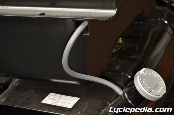
Disconnect the breather hose.
Relieve the fuel pressure and disconnect the fuel hose from the fuel pump. See the Fuel Pump topic for more information.
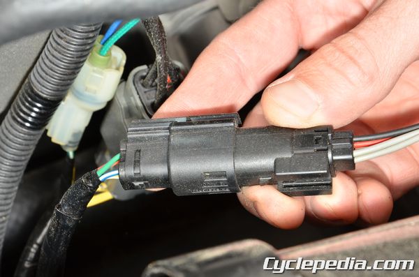
Unplug the fuel pump connector.
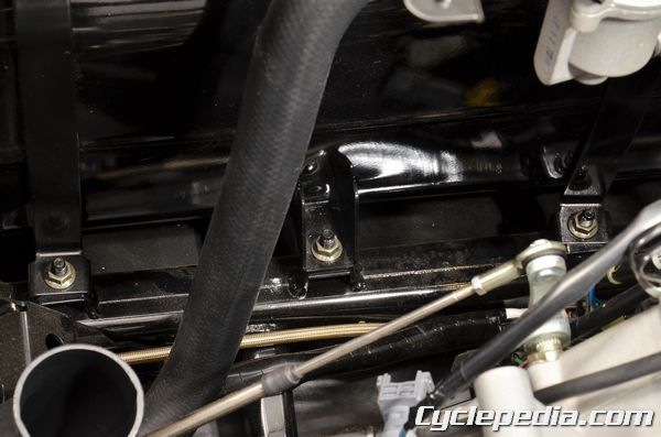
Remove the three fuel tank mounting nuts using a 12 mm socket.
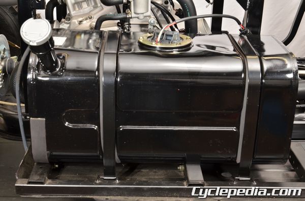
The fuel tank is secured by two mounting straps.
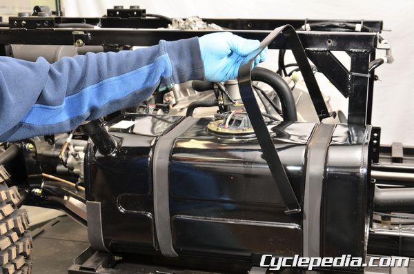
Remove the two fuel tank straps.

Remove the fuel tank from the frame.
Installation is the reverse of removal. Be sure to tighten the three fuel tank mounting nuts securely.
Fuel Pump
SAFETY FIRST: Protective gloves and eyewear are recommended at this point.Warning: Gas is extremely flammable! Do not work around an open flame or a source of sparks.
Fuel Pressure Relief
Remove the seat. See the Seat topic for more information.In order to release fuel pressure from the fuel hose, unplug the fuel pump connector. Start the engine and let it run until it dies of fuel starvation. Turn the ignition switch off. Reconnect the fuel pump connector.
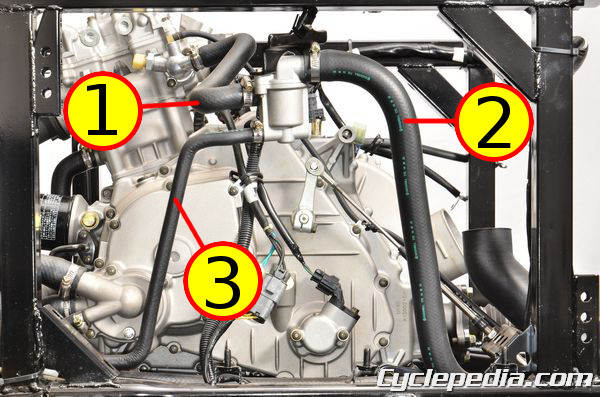
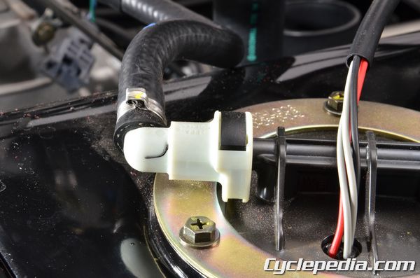
Fuel Line Inspection
Remove the seat. See the Seat topic for more information.Remove the right storage box. See the Seat Cross Pipe for more information.
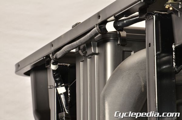
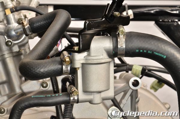
Note the routing of the fuel line from the fuel pump to the throttle body. Inspect the fuel line and replace as needed.
Input Voltage Inspection
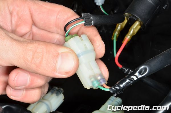
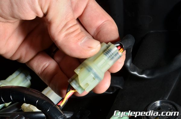
Unplug the fuel pump connector.
Set the multimeter to read voltage (DCV).
Touch the multimeter leads to the harness side of the fuel pump connector, with the positive lead touching the orange/red wire terminal and the negative lead touching the green wire terminal.
Turn the ignition switch ON. The battery voltage should show for a few seconds. Replace the fuel pump if it is not functioning and the input voltage is correct.
If the battery voltage is not present check the following:
- Fuse B (10 A)
- Fuel pump relay
- ECU
Fuel Output Pressure
Turn the key to the OFF position.
Use a fuel hose clamp to block the flow of fuel to the fuel injector. Disconnect the fuel hose from the fuel injector pipe. Connect the fuel pressure gauge to the fuel hose. Remove the fuel hose clamp. Turn the key to the ON position. Check the fuel pressure.
Fuel Pump Standard Pressure (at 80 L/Hr): 300 ± 10 kPa (43.5 psi)
If the fuel output pressure is less than the specifications If the fuel pressure is below specification check the fuel line for kinks and clogs. Inspect the fuel strainer screen on the fuel pump and the breather hose on the tank.
Fuel Pump Relay
Turn the key to the OFF position.Open the hood. See the Hood for more information.
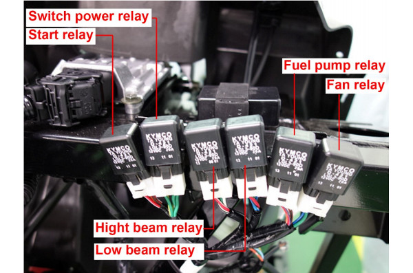
The fuel pump relay is located near the ECU.
Lift the fuel pump relay off of the finger on the frame.
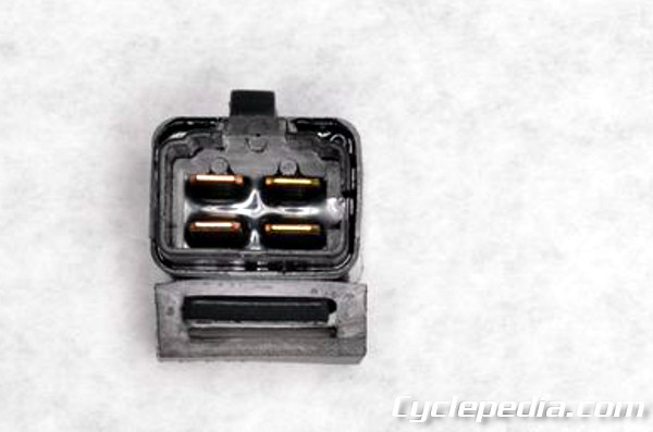
Remove the fuel pump relay from the connector.
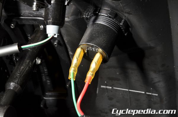
Continuity Test
Set the multimeter to read ohms of resistance.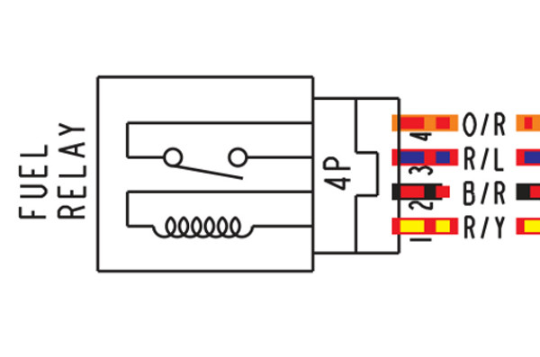
Check for continuity between the terminals of the relay that match up with the red/blue and orange/red wires.
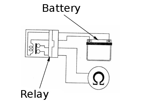
Jump a 12 V battery to the terminals of the relay that match up with red/yellow and black/red wires. There should be continuity only when 12 V battery connected. If there is not continuity when the 12 V battery is connected, replace the fuel pump relay.
Fuel Pump Removal
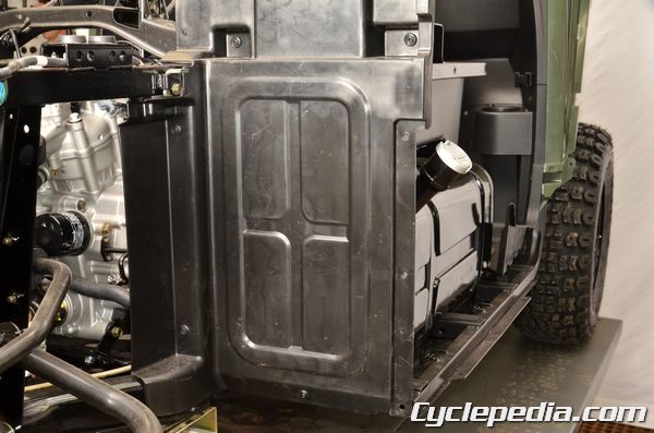
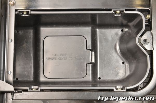
Turn the ignition switch off.Remove the right storage box or at least remove the fuel pump cover.
Unplug the fuel pump connector.
Remove the gas cap to normalize the pressure in the tank. Install the gas gap. With the fuel pump connector still unplugged start the engine and allow it to run until it uses the remaining fuel in the line and stalls. Turn off the ignition switch after the engine stalls.
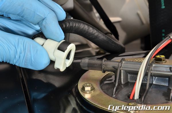
Clean the disconnect fitting and put a rag over it.
Push down on the black release and disconnect the fuel fitting from the fuel tank. Place plastic bags over the fuel line ends to keep debris out and prevent damage.
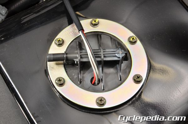
Remove the six fuel pump bolts with a 10 mm socket.
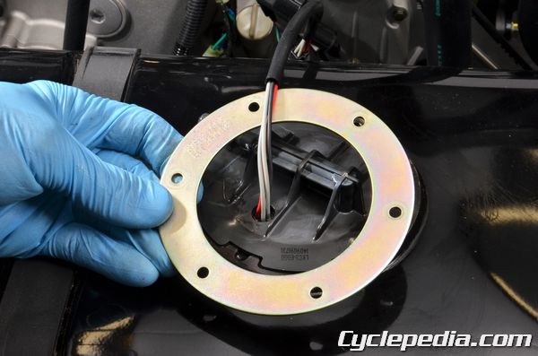
Remove the fuel pump mounting ring.
Carefully lift out the fuel pump.
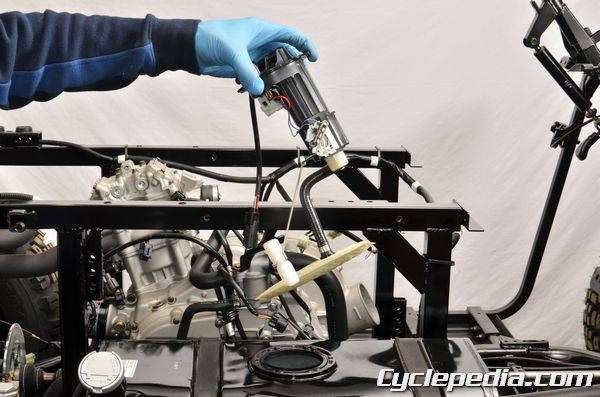
Guide the fuel level float out of the fuel tank with the pump.
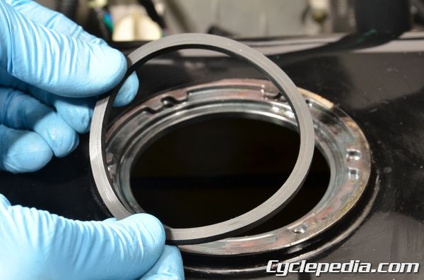
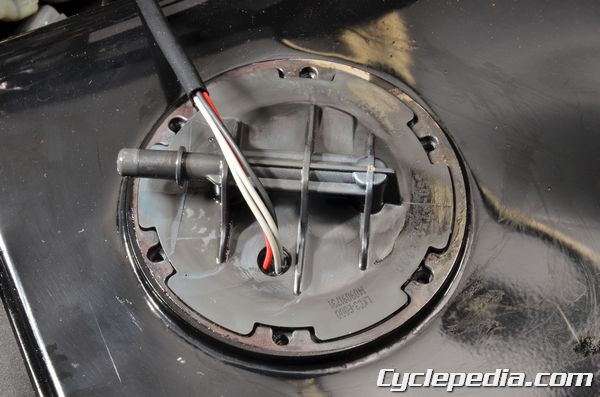
Remove the O-ring from the fuel pump. Discard the fuel pump O-ring, and replace it with a new item on assembly.
Fuel Level Gauge Inspection
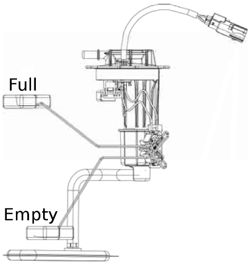
Make sure the fuel level gauge float arm moves smoothly. Using a digital multimeter set to ohms of resistance (Ω). Measure the resistance between the gray wire fuel pump/level gauge connector terminals with the float raised to the positions indicted below.
Fuel pump resistance (at 20 degrees C/68 degrees F)Float at full position: About 101 ohms
Float at empty position: About 3 ohms
Replace the fuel pump unit with a new part if the resistance is out of specification.
Fuel Pump Installation
Replace the O-ring with new item and apply a small amount of fresh engine oil to the new O-ring.
Carefully insert the fuel pump into the tank. Avoid damaging the fuel pump wires and fuel strainer.
The fuel delivery pipe should face to the rear left corner of the fuel tank.
Install mounting plate and the six fuel pump bolts. Tighten the bolts evenly to specification with a 10 mm socket.
Fuel Pump Bolts: 0.35 Kgf-m (3.5 N-m, 2.5 ft-lb)
Connect the fuel hose to the outlet pipe on the fuel pump. Make sure the connector is securely attached to the outlet pipe.
Plug in the fuel pump connector.
Install the fuel pump cover or the right storage box. See the Seat Cross Pipe for more information.
Install the seat. See the Seat topic for more information.
Diagnostic Trouble Codes
To evaluate the DTCs see the Check Engine Lamp (CELP) and Diagnostic Tool topics.| Blinks | Failure Codes | Fault description | Priority | Fault management |
| 1 | P0217 | Engine temperature overheat | 1 | 1.Stop immediately and check CELP code. 2. Check if the engine temperature sensor or electric circuit is faulty. 3. Check engine lubrication and cooling systems. 4. Check engine ignition and fuel systems. |
| 2 | P0335 | Crankshaft position sensor or circuit malfunction | 2 | 1. Check if the crankshaft position sensor, its connector, or wiring is faulty. 2. Make sure the generator rotor is aligned with the crankshaft position sensor. |
| 3 | P1120 | Throttle position sensor setting value problem | 2 | 1.Check if the TPS connector or wiring is faulty. 2.Check if the TPS is adjusted. |
| 4 | P1121 | Throttle position sensor output range problem | 2 | 1. Make sure the TPS connector is connected correctly. 2. Inspect the TPS |
| Blinks | Failure Codes | Fault description | Priority | Fault management |
| 5 | P1122 | Throttle position sensor movement speed problem | 2 | 1. Make sure the TPS connector is connected correctly. 2. Inspect the TPS adjustment. |
| 6 | P0560 | Battery voltage malfunction | 1 | 1. Check the battery voltage. 2. Inspect the charging system. |
| 7 | P0110 | Intake air temperature circuit malfunction | 2 | Inspect the T-MAP sensor |
| 8 | P0410 | Idle air valve circuit malfunction | 2 | 1. Check if the ISC connector or wiring is faulty. 2. Check the resistance of the idle air valve. |
| 9 | P0505 | Idle speed volume control range problem | 3 | 1.Check the ISC steps range with the diagnostic tool. 2. Check throttle body for carbon deposits. 3. Check intake for air leaks |
| 10 | P0251 | Injector or electric circuit problem | 2 | 1. Make sure the fuel injector connector is connected correctly. 2. Check if the ECU sends a signal to the injector. 3. Check the power source and resistance of the injector. 4. Make sure the battery is fully charged and connected correctly. |
| Blinks | Failure Codes | Fault description | Priority | Fault management |
| 11 | P0350 | Ignition coil or electric circuit malfunction | 2 | 1. Make sure the ignition coil connector is connected correctly. 2. Check if the ECU sends a signal to the ignition coil. 3. Check the ignition coil power source and resistance. 4. Make sure the battery is fully charged and connected correctly. |
| 12 | P0230 | Fuel pump relay or electric circuit malfunction | 2 | 1. Make sure the relay and pump connectors are connected correctly. 2. Check if the ECU sends a signal to relay. 3. Check the fuel pump relay resistance |
| 13 | P0219 | Engine speed has exceeded top speed | 2 | Check if the CVT belt is broken. |
| 14 | P1560 | Sensor doesn’t receive power source from ECU | 2 | 1. ECU output to each sensor should be 5 DCV. 2. Check if the power source for all sensors is 5 DCV. 3. Check for a problem in the wiring harness. 4. If the CELP still blinks replace the ECU with a new item even if the output power source of ECU is normal. |
| 15 | P0700 | Engine starting speed exceed CVT speed limited | 2 | Not used. |
| 16 | P0115 | Engine temperature sensor or electric circuit malfunction | 2 | 1. Make sure the WTS connector is connected correctly. 2. Check if the ECU pin is broken. 3. Check if the resistance of the sensor is out of specification. |
| 17 | P1561 | Temperature gauge electric circuit malfunction | 2 | Not used. |
| Blinks | Failure Codes | Fault description | Priority | Fault management |
| 18 | P0650 | CELP electric circuit malfunction | 3 | 1. Check if the CELP bulb is faulty. 2. Check the CELP wires for damage. |
| 21 | P0105 | Atmospheric Pressure Sensor/Circuit Malfunction | 2 | 1. Make sure the MAP sensor connector is connected correctly. 2. Check ECU for broken pins. 3. Check the sensor voltage. 4. Use Diagnostic Tool to check the pressure. |
| 22 | P0110 | Roll sensor or electric circuit malfunction | 2 | 1. Make sure the sensor is installed in the correct position. 2. Check the sensor voltage. 3. Check ECU for broken pins. |
Diagnostic Tool
SAFETY FIRST: Protective gloves and eyewear are recommended at this point.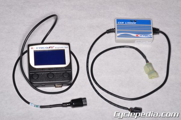
Diagnostic tool Part Number: 3620A-LEB2-E00
CAN Linker Part Number: 3620A-LGC7-E000
This tool has been developed by KYMCO for KYMCO vehicles only.
The tool software can be updated for new models with a computer via the USB cable.
Please refer to the specifications when servicing this vehicle. See the Specifications topic for more information.
UXV 450i Diagnostic Report ON-ROAD
UXV 450i Diagnostic Report OFF-ROAD
This tool does not have an internal battery. The power for the tool is provided by the vehicle when connected. The vehicle should have a fully charged battery when using the diagnostic tool.
Set the transmission shifter in the P or N position.
Plug the diagnostic tool connector into the CAN Linker.
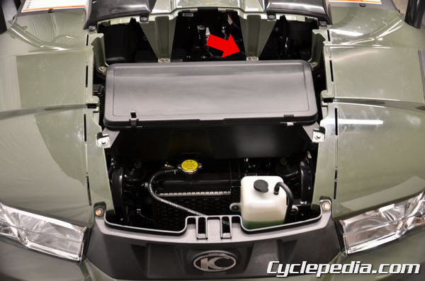
Remove the hood to access the diagnostic connector. See the Hood topic.
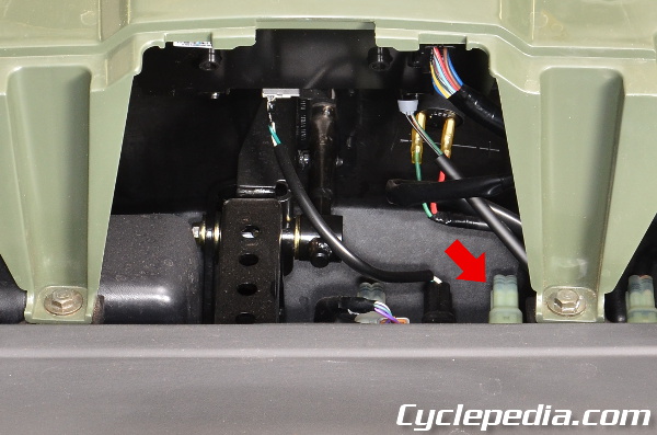
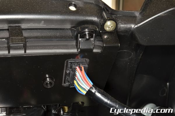
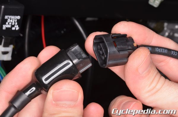
The diagnostic connector is located behind the front storage box.
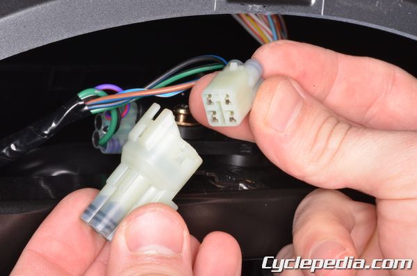
Remove the dummy side of the connector.
Set a multimeter to reads voltage (DCV). Measure the voltage as indicated.
| Terminal (+) | Terminal (-) | Normal |
| BR/L | G/B | Battery Voltage |
| B/L | W/L | Battery Voltage – 1 |
Turn on the ignition switch to send power to the tool.

The FI tool has three buttons and two lights below the screen. The left button is the up button that will move the selector up. The right button is the down button that moves the selector down. The middle button is ENTER. This will select the item you have chosen. The left light indicated the tool has power, and the right light indicates a Diagnostic Trouble Code (DTC) is present.
The functions of the diagnostic tool include ECU version, model name, data analysis and adjust.
ECU version: includes model name, ECU number, identifications number and software version.
DTC Inspect: DTC reading, DTC clearing, and troubleshooting.
Data Analyze: For ECU’s setting inspection and running condition analysis.
Adjust: Not allowed
ECU Version
The four functions will display when the tool is powered on. The model name will show LKC3 for the UXV500i and ALE8 for the UXV450i.

Pressing the enter button on the ECU version will show information on the ECU software and calibration.
Press the down button (right) to return to the first page.
DTC INSPECTION PROCEDURE
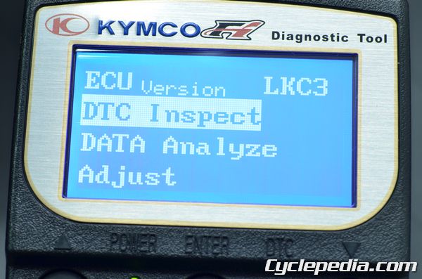
Press the down button (right) to move the item selector down to the DTC Inspect item.

Pressing the enter button on the DTC Inspect item will bring up the options shown above. Select the DTC Load option and press the enter button to display the DTC options.

There are three DTC options – Active, Occurred, and History.
Move the selector to the Active option and press enter to display current DTC.
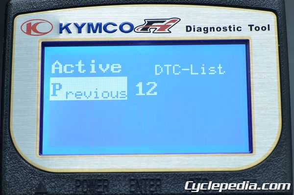
The diagnostic tool will display all current DTC. In the photo above only one code (12) is showing. Select the code number of interest and press enter for more information on that DTC.
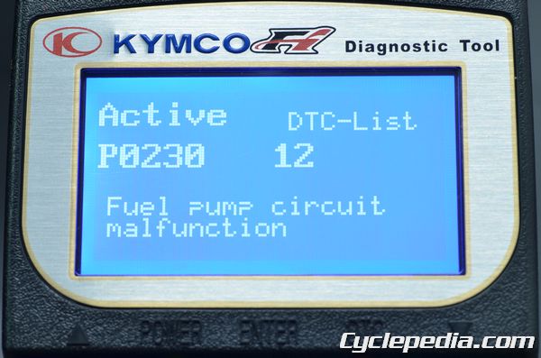
In this instance the indicated code is 12 (CELP blinks). This corresponds to the DTC P0230.
| Blinks | Failure Codes | Fault description | Priority | Fault management |
| 11 | P0350 | Ignition coil or electric circuit malfunction | 2 | 1. Make sure the ignition coil connector is connected correctly. 2. Check if the ECU sends a signal to the ignition coil. 3. Check the ignition coil power source and resistance. 4. Make sure the battery is fully charged and connected correctly. |
| 12 | P0230 | Fuel pump relay or electric circuit malfunction | 2 | 1. Make sure the relay and pump connectors are connected correctly. 2. Check if the ECU sends a signal to relay. 3. Check the fuel pump relay resistance |
Up button and select the previous options to return to the original screen.
DTC Clear Procedure
Press the down button (right) to move the item selector down to the DTC Inspect item.

Pressing the enter button on the DTC Inspect item will bring up the options shown above. Move the selector down to the Clear DTC option and press enter.
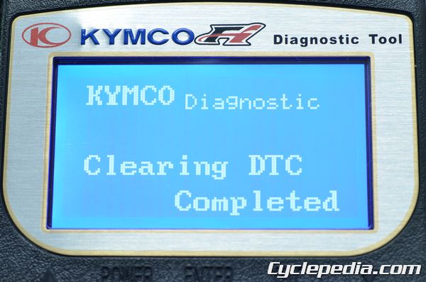
The diagnostic tool will show when the DTC in memory is cleared. Also, the DTC indicator light will be off.
Data Analysis Procedure
When using the data analysis feature for running condition items such as ignition advance, ISC step, ect., make sure the engine temperature has reached 80° C. The engine temperature is displayed on data analysis page 03.
Press the down button (right) to move the item selector down to the DATA Analyze item. Press enter to bring up the DATA Analyze page 01 shown below. Press the down button to continue through the seven DATA Analyze pages.
Page 01
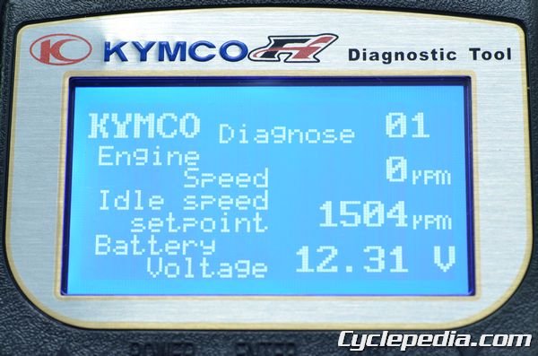
The 01 page shows engine speed, idle speed set point, and battery voltage.
Page 02
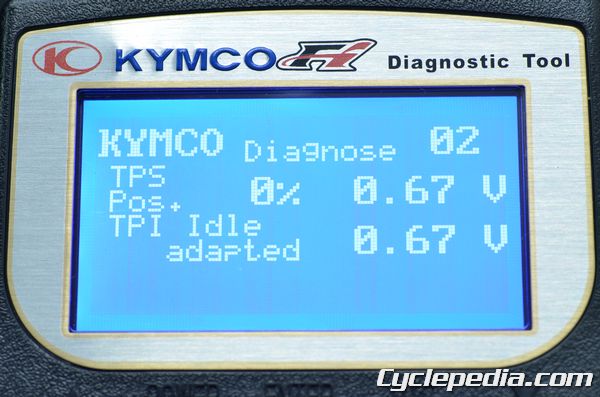
The 02 page shows TPS position and TPI idle adapted.
Page 03
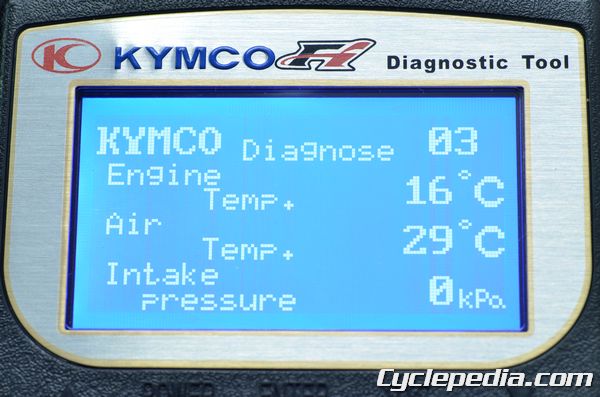
The 03 page shows engine temperature, air temperature, and intake pressure.
Page 04
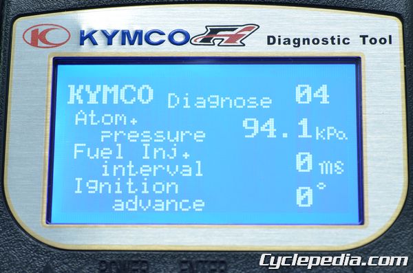
The 04 page shows atmospheric pressure, fuel injection interval, and ignition advance.
Page 05
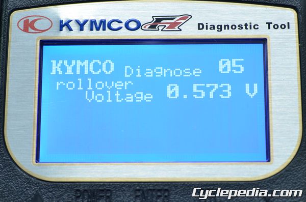
The 05 page shows the rollover voltage.
Page 06
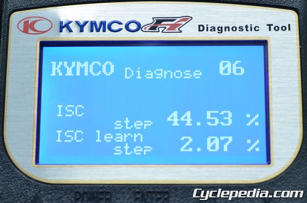
The 06 page shows the ISC step and ISC learn step.
Page 07
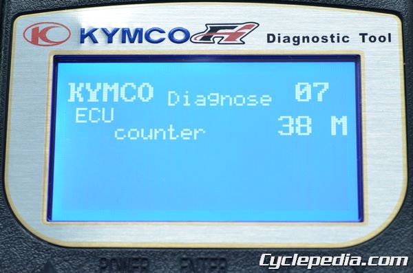
The 07 page shows the ECU counter.
Check Engine Lamp
SAFETY FIRST: Protective gloves and eyewear are recommended at this point.Note: The check engine lamp (CELP) will come on for 2 seconds when the key is turned on and then it should go off. If it lights after this the system has detected a problem. The vehicle should be immediately diagnosed as to what is causing the light to come on.
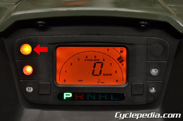
The check engine lamp (CELP) is located on the instrument display.
If the ECU connectors, or battery leads are disconnected the stored malfunction codes will be lost.
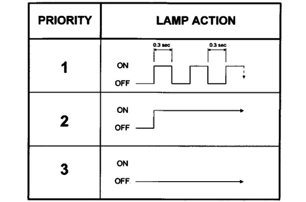
There are 3 priority levels of the CELP while the engine is running.
Priority grade 1: The CELP blinks continuously letting you know this is the most severe condition. The rider must slow and immediately take the vehicle to the dealership service center for evaluation.
Priority grade 2: The CELP lights and doesn’t blink, but stays on continuously. This shows a component is experiencing trouble or something has gone wrong with a circuit. Evaluate the trouble code to find the source of the problem.
Priority grade 3: The CELP blinks once and doesn’t come back on. This is a warning. Example – the engine rpm was too high for a short time.
Self-Diagnostic Procedures
(Without Diagnostic Special Tool)
● Turn key to the ON position.● The CELP will light for two seconds and then go off.
● If the engine has problem, the CELP will blink to show the failure codes.
● There’re 22 failure codes for the Synerjet M3C system.
If the vehicle gets multiple failure codes, the CELP will display the lower number code, then progress to the higher number after four seconds. The failure codes will display repeatedly. After the codes cycle four times the codes will clear from the system memory.
Efi Self-Diagnosis Failure Codes
The CELP denotes the failure codes. When the indicator lights for one second that is equal to ten. A half second blink is equal to one.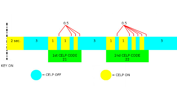
In the example above the first code has two long blinks (10 X 2) and one short blink (+ 1). This equals 21 blinks.
(10 X 2) + 1 = 21
The second code in the example shows three seconds after the first. The second code has two long blinks (10 X 2) and two short blinks (+ 2). This equals 22 blinks.
(10 X 2) + 2 = 22
In this example the failure codes corresponding with 21 and 22 blinks need to be evaluated.
To see the full list of trouble codes see the Diagnostic Trouble Codes (DTCs) topic.
With Special Tool
See the Diagnostic Tool topic.Self-Diagnosis Reset Procedure
After the codes cycle four times the codes will clear from the system memory. Always clear the memory after fixing the problem to prevent the light from showing the next time the vehicle is used.TPS/ISC Reset
Start the engine and let it idle until the engine temperature has reached 85° C (185° F). The ECU will learn the new setting.Throttle Body
SAFETY FIRST: Protective gloves and eyewear are recommended at this point.- Turn off the ignition switch during removal/installation.
- Check and confirm if the voltage is over 12V with a voltmeter after replacement.
- Check and confirm if the other connectors are installed correctly after replacement.
- Do not damage the throttle body, it may cause the throttle and idle valve to fail synchronization.
- The throttle body is preset in the KYMCO factory, do not disassemble it incorrectly.
- Do not loosen or tighten the painted bolts and screws for the throttle body. Loosening or tightening them can cause the throttle and idle valve synchronization to fail.
- TPS and ISC have to be reset after the throttle body MAP, TPS, ISC or ECU has been reinstalled.
Throttle Body Removal
Remove the following components: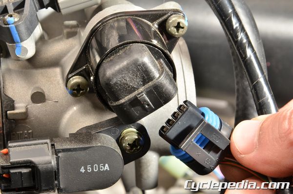
Unplug the ISC connector.
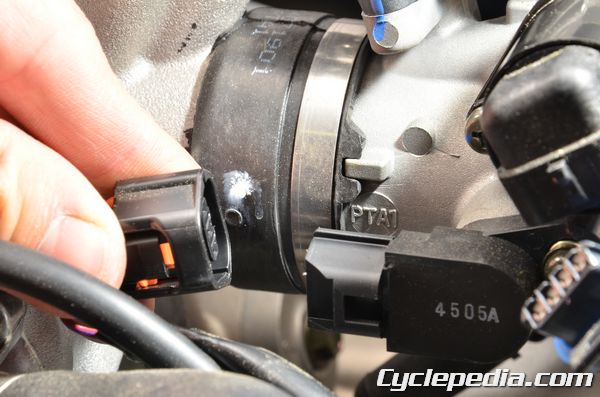
Unplug the TPS connector.
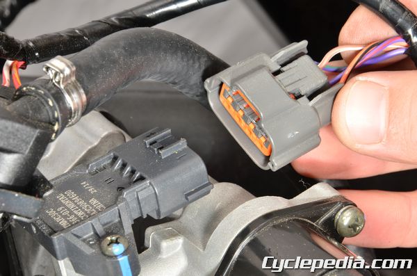
Unplug the T-MAP connector.
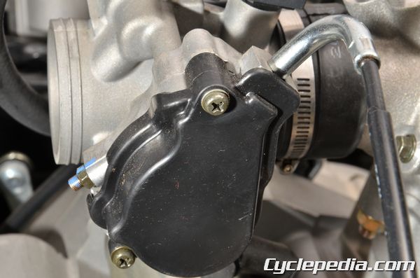
Remove the two throttle drum cover screws.
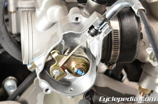
Remove the throttle drum cover. Slide the throttle cable housing out of the throttle body.
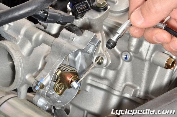
Free the throttle cable from the throttle drum.
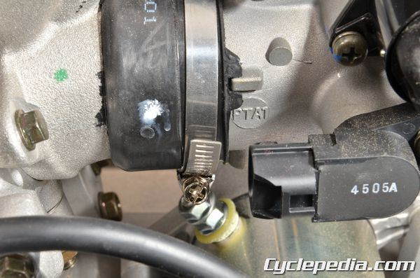
The throttle body is held to the intake pipe with a clamp. Loosen the intake pipe clamp with a #2 Phillips screwdriver.
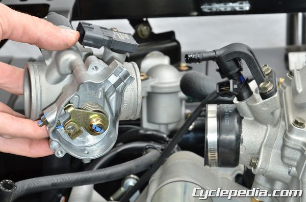
Remove the throttle body from the intake pipe.
Intake Pipe
Remove fuel injector. See the Fuel Injector topic for information.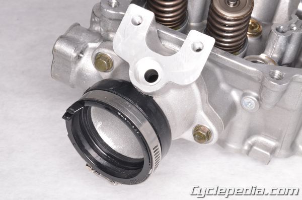
Remove the two intake pipe bolts that hold the intake pipe to the cylinder head.
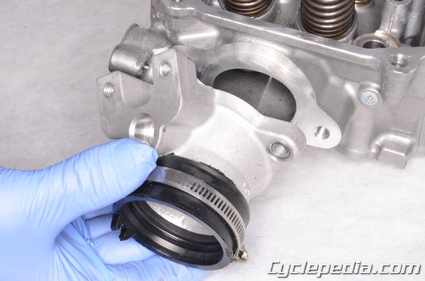
Remove the intake pipe from the cylinder head.
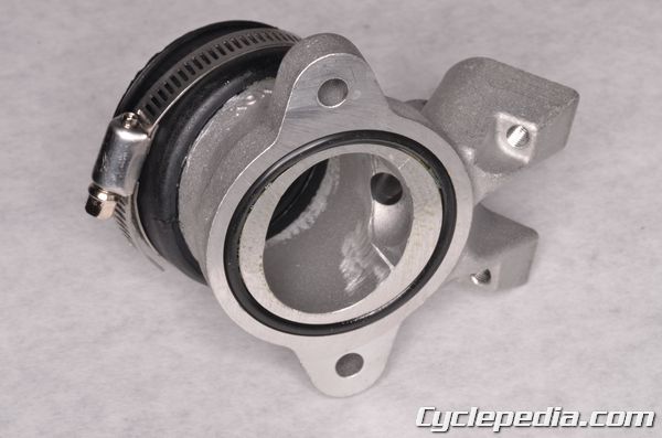
Remove the O-ring from the intake
To disassemble the throttle body see the Throttle Body Components topic for more information.
Throttle Body Installation
Intake Pipe
Install a new intake pipe O-ring. If this O-ring allows an air leak the engine will not run correctly.Fit the intake pipe onto the cylinder head. Install the intake pipe and tighten the bolts securely with a 10 mm socket.
Install the fuel injector. See the Fuel Injector topic for information.
Throttle Body
Fit the throttle body into place. Make sure the ridge on the throttle body fits into the gap on the intake pipe fitting.
Tighten the intake pipe throttle body clamp securely with a #2 Phillips screwdriver.
Fit the end of the throttle cable into the throttle drum. Fit the throttle cable into the throttle body.
Install the throttle drum cover. Install the two throttle drum cover screws and tighten them securely with a #2 Phillips screwdriver.
Plug in the T-MAP connector.
Plug in the TPS connector.
Plug in the ISC connector.
Inspect the throttle freeplay. See the Throttle Free Play topic for more information.
Install the following components:
Fuel Injector
SAFETY FIRST: Protective gloves and eyewear are recommended at this point.Warning: Gas is extremely flammable! Do not work around an open flame or a source of sparks.
Fuel Pressure Relief
Remove the seat. See the Seat topic for more information.In order to release fuel pressure from the fuel pipe when removing the fuel injector, unplug the fuel pump connector. Start the engine and let it run until it dies of fuel starvation. Turn the ignition switch off. Reconnect the fuel pump connector.
See the Fuel Pump topic for more information on the fuel pump.
Fuel Injector Removal
Remove the seat. See the Seat topic for more information.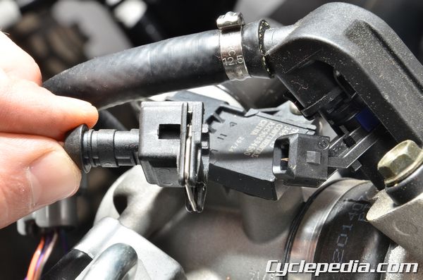
Push in the spring clip and unplug the fuel injector connector.
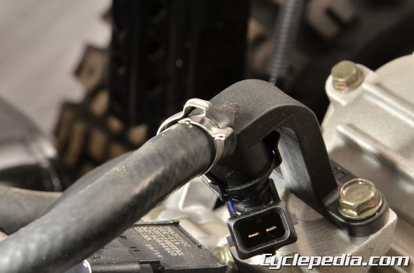
Open the fuel injector hose clamp.
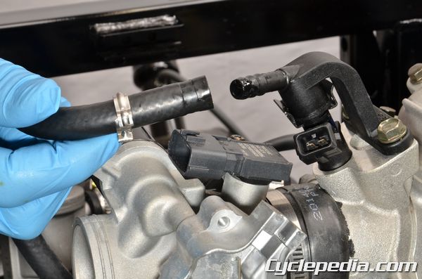
Disconnect the fuel hose from the fuel injector.
Fuel Injector Disassembly
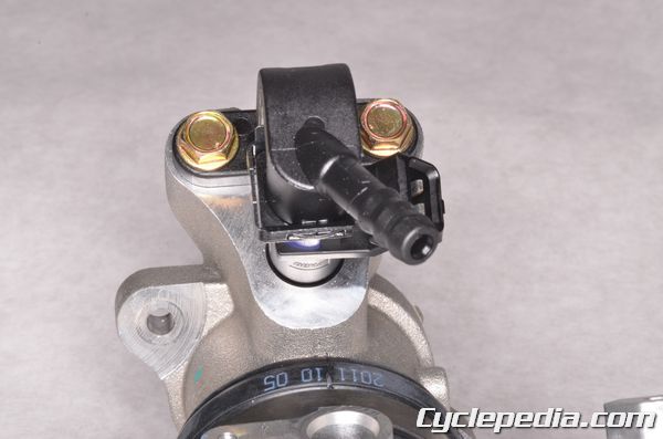
Remove the two fuel injector mounting bolts with a 10 mm socket.
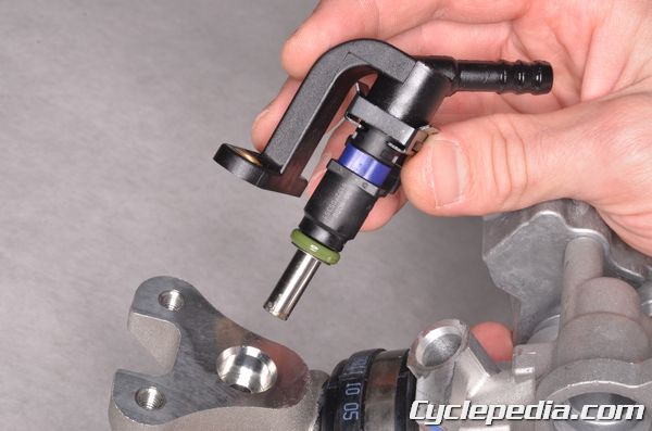
Remove the fuel injector and pipe from the intake pipe.
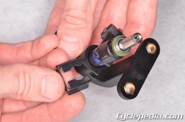
Slide off the clip.
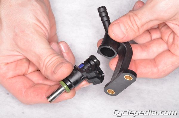
Pull the fuel injector out of its pipe. Discard the O-rings.
Fuel Injector Inspection
A digital multimeter is needed to test the fuel injector. Set the multimeter to read ohms of resistance.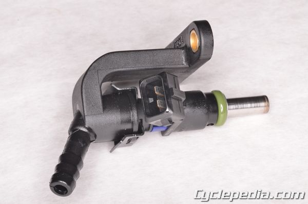
Measure the resistance between the fuel injector terminals
Fuel injector resistance (at 20 degrees C/68 degrees F): 10.6-15.9 ohms
Fuel Injector Cleaning
Problem
- Fuel Injector will not dispense fuel.
- The Injector injection time (ms) is shorter or longer.
Analysis
Injector block (With carbon build up).Solution
- Use the specified injector cleaner.
- Connect the battery as pictured.
- The injector cleaner with the flash relay.
- Keeping the fuel injector operating.
- Wait for 20-30 minutes.
- Clean the carbons completely from the injector.
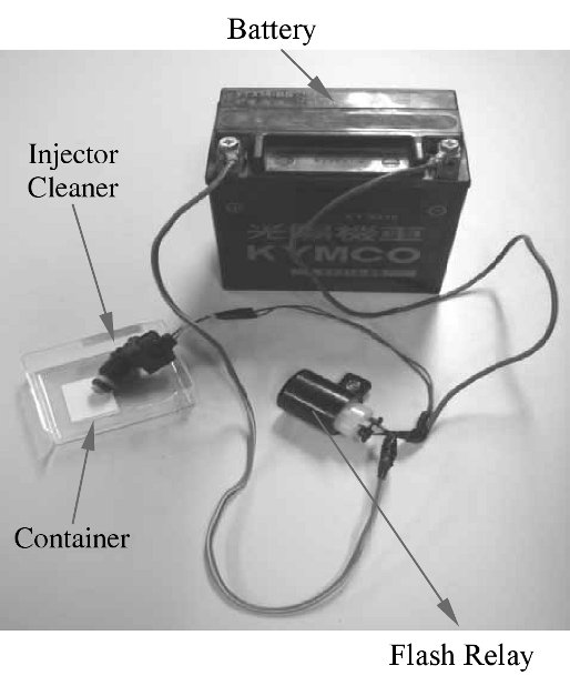
Fuel Injector Assembly
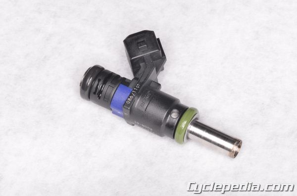
Install new O-rings on the fuel injector. Apply a light coat of fresh engine oil to the fuel injector O-ring seals.
Install the fuel injector into the pipe. Install the clip to secure the fuel injector.
Install fuel injector and pipe onto the intake pipe. Guide the fuel injector into place, and be sure not to damage the O-ring. Install the two fuel injector mounting bolts and tighten them securely.
Fuel Injector Installation
Use a new clamp on the fuel hose.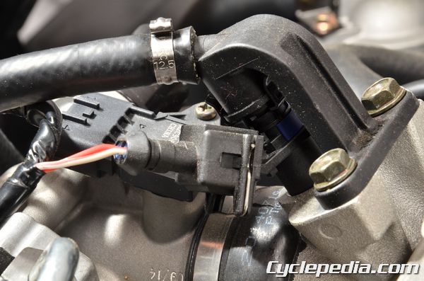
Connect the fuel hose to the fuel injector pipe. Secure the new clap on the fuel hose. Plug in the fuel injector connector.
Install the seat. See the Seat topic for more information.
Disassembly
Fuel Injector
See the Fuel Injector topic for information.T-MAP Sensor
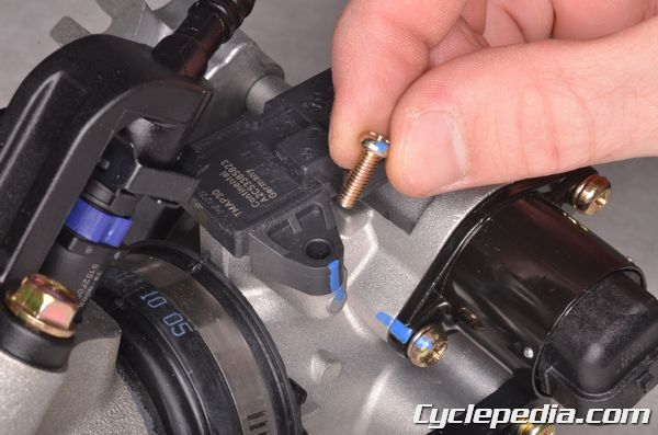
The T-MAP sensor sits on top of the throttle body. Remove the T-MAP sensor set plate screw with a #2 Phillips screwdriver.
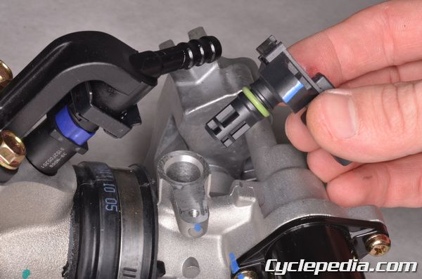
Remove the T-MAP sensor.
ISC (Idle Speed Control – Air Bypass Valve)
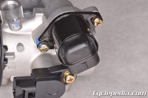
Remove the two ISC screws with a #2 Phillips screwdriver.
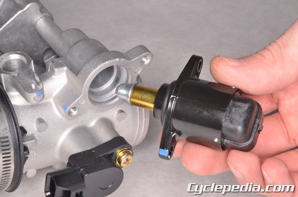
Remove the ISC from the throttle body. Remove the O-ring from the ISC and discard it. Clean the tip of the ISC valve.
Inspection
If the engine is hard to start, stops, or idles rough the ISC may be faulty.Use the data analysis feature of the FI Diagnostic Tool to see information on the ISC. See the Diagnostic Tool topic for more information.
Start the engine and let it run until the engine temperature reaches 80° C.
The ISC step should be below 65.
TPS Sensor
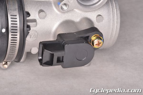
The TPS is located on the throttle shaft opposite the throttle drum. Remove the TPS sensor with a #2 Phillips screwdriver.
Assembly
The throttle position sensor (TPS) and idle air bypass valve (ISC) have to be reset when the throttle body MAP, TPS, ISC or ECU have been reinstalled.TPS/ISC Reset
Start the engine and let it idle until the engine temperature has reached 85° C (185° F). The ECU will learn the new setting.TPS Sensor
Apply oil onto a new O-ring and place it on the TPS.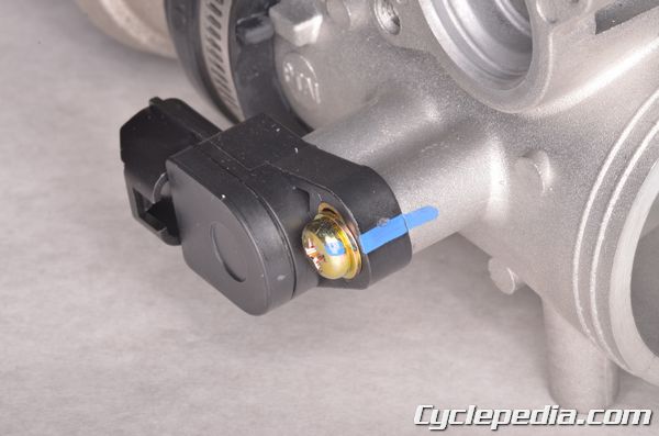
Install the TPS onto the throttle body so that it returns to the original position. Install and tighten the screw securely with a #2 Phillips screwdriver.
ISC (Idle Speed Control – Air Bypass Valve)
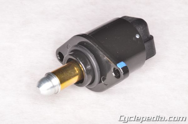
Apply oil onto a new O-ring and place it on the ISC.
Install the ISC into the throttle body, being careful not to damage the O-ring. Install the two ISC screws and tighten them securely with a #2 Phillips.
T-MAP Sensor
Apply oil onto a new O-ring and place it on the T-MAP sensor. Install the T-MAP into the throttle body, being careful not to damage the O-ring.
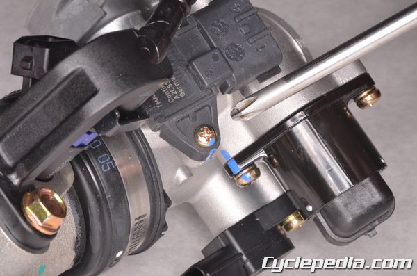
Install the T-MAP sensor screw and tighten it securely with a #2 Phillips.
Install the throttle body. See the Throttle Body topic for more information.
FI Sensors
SAFETY FIRST: Protective gloves and eyewear are recommended at this point.You will need a digital multimeter to inspect the sensors.
Water Temperature Sensor (WTS)
Removal
Remove the Cargo bed. See the Cargo Bed topic for more information.Drain the coolant. See the Coolant topic for more information.
Turn the ignition switch to the OFF position.
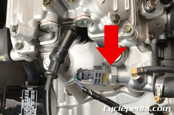
The WTS is located on the side of the cylinder head near the spark plug.
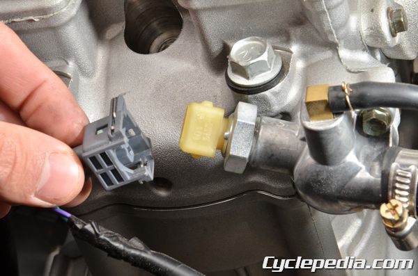
Push in the spring and unplug the WTS sensor connector.
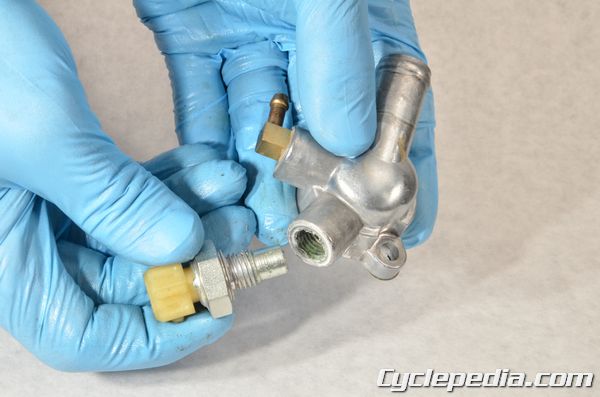
Remove the sensor with a 22 mm wench.
Installation
Thread in the WTS. Tighten the WTS to specification with a deep well 22 mm socket.Water Temp Sensor: 12 Nm, 1.2 kgf-m, 8.6 ft-lb
Inspection
Input Voltage
Turn the ignition switch to the OFF position.Push in the spring and unplug the WTS sensor connector.
Set the multimeter to read voltage (DCV).
Turn the ignition switch to the ON position.
Measure the input voltage on the harness side of the connector.
WTS Input Voltage: 5 ± 0.1 V
If the input voltage is out of specifications check the offending wires for a short or open lead.
Resistance
Set the multimeter to ohms of resistance.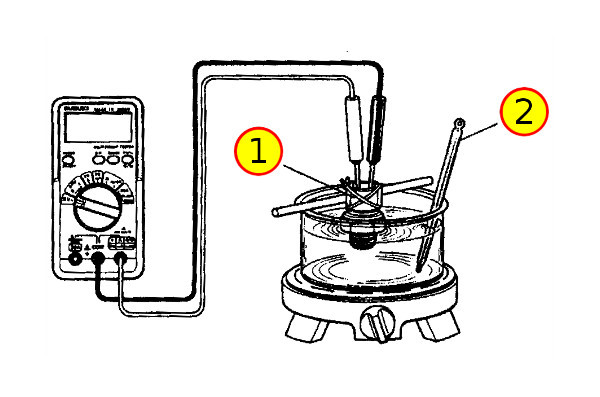
Suspend the sensor (1) and a thermometer (2) in a pot of coolant with string. Make sure the WTS and the thermometer are not touching the pot. Bring the temperature up to the specification slowly and check the resistance between the sensor terminal and body.
Temperature: Standard Resistance (approximate)
-20° C (-4° F): 28.6 kΩ
20° C (68° F): 3.51 ± 10% kΩ
40° C (104° F): 1.46 kΩ
100° C (212° F): 0.176 kΩ
Temperature and Manifold Absolute Pressure (T-MAP)
To remove and install the sensors on the throttle body see the Throttle Body Components topic.Inspection
Input Voltage
Turn the ignition switch to the OFF position.Unplug the T-MAP connector.
Set the multimeter to read voltage (DCV).
Turn the ignition switch to ON position.
Measure if the ECU voltage outputs to the MAP between the following terminals of the MAP connector.
Violet/Red (+) to Violet/Green (-): 5 V
If the input voltage is out of specifications check the offending wires for a short or open lead.
Resistance
Set the multimeter to ohms of resistance.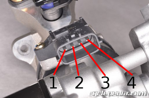
Measure the resistance between the 3 and 4 pins of the T-MAP sensor.
T-MAP sensor resistance (20°C): 1613 – 2544 ohms
To replace the T-MAP sensor see the Throttle Body Components topic.
Throttle Position Sensor
Inspection
Input Voltage
Unplug the TPS connector.
Turn the ignition switch to “ON”.
Measure if the ECU voltage outputs to TPS between the following terminals of the TPS connector.
Violet/Red (+) to Violet/Green (-): 5 V
Resistance
Set the multimeter to ohms of resistance.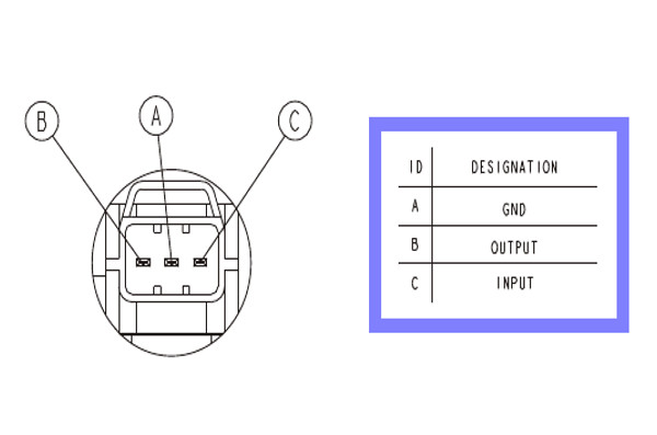
Measure the resistance between the ground (A) and input (C) terminals of the TPS.
Throttle position sensor (TPS) resistance (at 20 degrees C/68 degrees F): 3500-6500 ohms
Data Analysis
Bring up data analysis page 02 to see information on the TPS. See the Diagnostic Tool topic for more information.The TPS voltage should display as indicated in the table per the throttle position.
| Throttle Position | Opening Angle | Standard |
| Close | ||
| Open | > 90 % |
Ignition Pulse Generator / Crank Position Sensor
To inspect the ignition pulse generator/crank position sensor see the Ignition System topic.To replace the ignition pulse generator/crank position sensor see the Generator Cover topic.
Roll Sensor / Tip-Over Switch
Removal and Installation
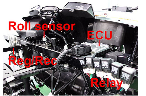
Remove the hood to access the roll sensor. See the Hood topic for more information.
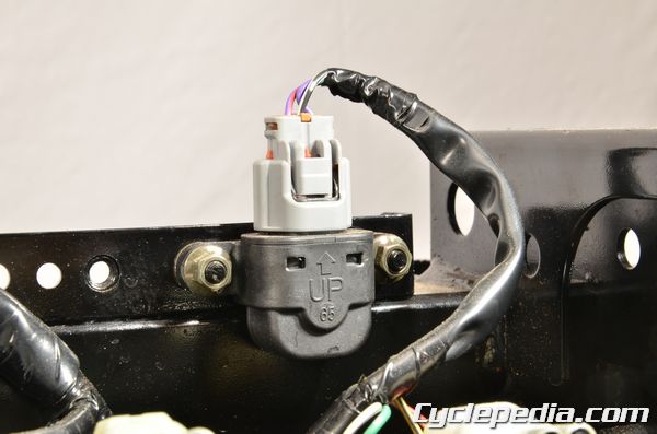
Remove the two roll sensor nuts. Unplug the roll sensor and remove it. Plug in the roll sensor and install it so the UP mark faces up.
Inspection
Turn the ignition switch to the OFF position.Remove the roll sensor screws, but leave the sensor plugged in.
Set the multimeter to read voltage (DCV).
Turn the ignition switch to the ON position.
Measure the voltage of the roll sensor wires with the connector plugged in and the sensor in the regular upright attitude.
Roll Sensor Voltage
Standard: 0.4-1.4 V
Over 65 degrees (fall down): 3.7-4.4 V
Incline the roll sensor 65 ± 10 degrees to the left or right. Check the voltage.
If this test is to be repeated the ignition switch must be turned OFF to reset the system.
Airbox
SAFETY FIRST: Protective gloves and eyewear are recommended at this point.Remove these components.
- Seat
- Air Filter – (if needed)
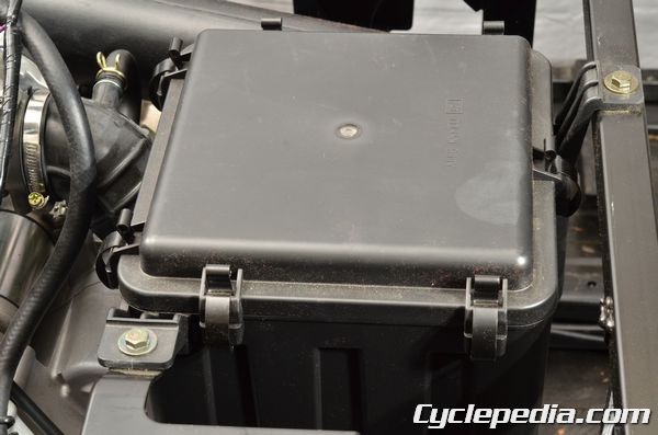
Remove the airbox mounting bolts with a 10 mm socket.
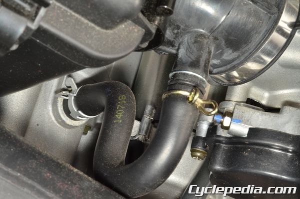
Disconnect the breather hose from the airbox boot.
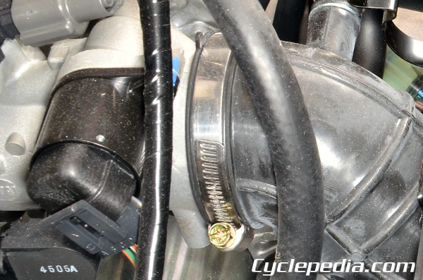
Loosen the airbox boot clamp with a #2 Phillips screwdriver.
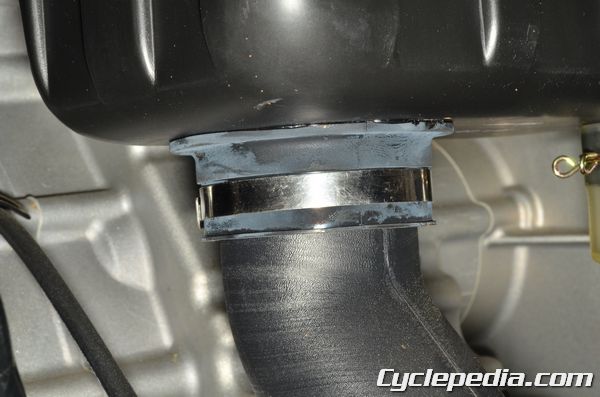
Loosen the air intake tube clamp with a #2 Phillips screwdriver.
Free the airbox from the throttle body and the air intake tube. Cover the throttle body mouth with a clean shop rag. Clean out the airbox.
Installation is the reverse of removal.
Engine Removal
SAFETY FIRST: Protective gloves and eyewear are recommended at this point.Remove the seat and backrest. See the Seat topic for more information.
Remove the cargo bed. See the Cargo Bed topic for more information.
Remove the heat shield mounting bolts with a 10 mm socket. Remove the heat shield.
Remove the exhaust system. See the Exhaust System chapter for more information.
Remove the splash panels and frame covers. See the Frame Covers topic for more information.
Remove the canopy bars. See the Canopy topic for more information.
Remove the seat cross pipe. See the Seat Cross Pipe topic for more information.
Drain the engine oil. See the Engine Oil topic for more information.
Drain the coolant. See the Coolant topic for more information.
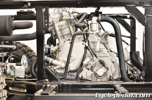
Disconnect the coolant hoses from the water pump cover and ECT housing.
Have a rag ready to clean up any fuel spills, free the clamp and disconnect the fuel line.
Remove the throttle body. See the Throttle Body topic for more information.
Remove the pinch bolt with a 10 mm socket and disconnect the gear shift linkage from the engine.
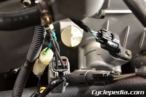
Unplug the speed sensor, stator and crank position sensor.
Remove the spark plug cap.
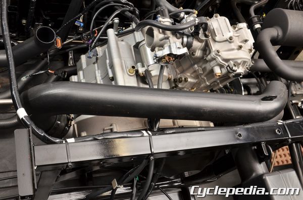
Remove the CVT cooling ducts. See the CVT Cover topic for more information.
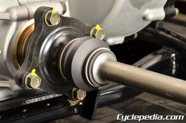
Remove the front and rear drive shaft bolts with a 12 mm socket.
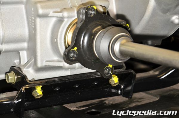
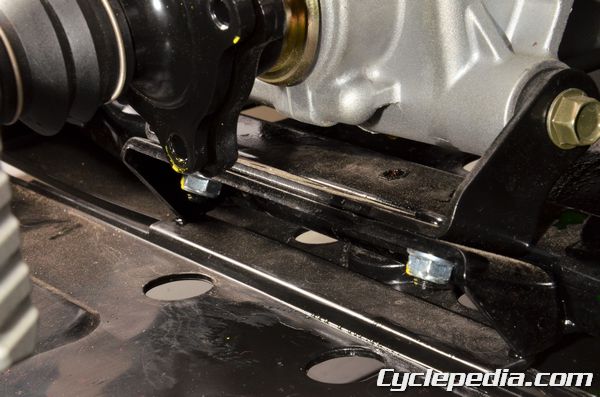
Remove the engine mounting bolts in the front and nuts in the rear with a 14 mm socket.
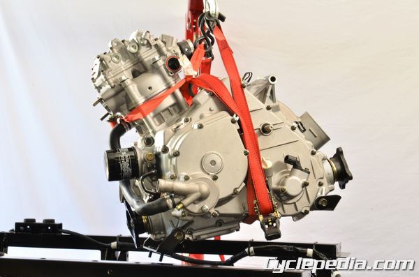
Secure the engine with a hoist or suitable crane and slowly lift the engine out of the frame.